IBM 867431X Hardware Maintenance Manual - Page 91
Preinstallation steps, Installing or replacing a hard disk drive, installing the drive.
 |
View all IBM 867431X manuals
Add to My Manuals
Save this manual to your list of manuals |
Page 91 highlights
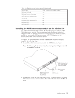
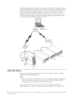
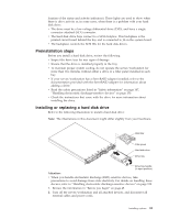
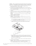
location of the status and activity indicators). These lights are used to show when there is drive activity or, in some cases, when there is a problem with your hard disk drive. v The drive must be a low voltage differential drive (LVD), and have a single connector attached (SCA) connector. v The hard disk drive bays connect to a SCSI backplane. This backplane is the printed circuit board behind the bay and is connected to J4 on the system board. v The backplane controls the SCSI IDs for the hard disk drives. Preinstallation steps Before you install a hard disk drive, review the following. v Inspect the drive tray for any signs of damage. v Ensure that the drive is installed properly in the tray. v To maintain proper system cooling, do not operate the server/workstation for more than two minutes without either a drive or a filler panel installed in each bay. v If your server/workstation has a ServeRAID adapter installed; refer to the documentation provided with the ServeRAID adapter for information about adding a drive. v Read the safety precautions listed in "Safety information" on page 147, "Handling electrostatic discharge-sensitive devices" on page 150. v Check the instructions that come with the drive for more information about installing the drive. Installing or replacing a hard disk drive Refer to the following illustration to install a hard disk drive: Note: The illustrations in this document might differ slightly from your hardware. Slim filler Filler panel Hard disk drive Drive tray Drive tray handle (in open position) Attention: v When you handle electrostatic discharge (ESD) sensitive devices, take precautions to avoid damage from static electricity. For details on handling these devices, refer to "Handling electrostatic discharge-sensitive devices" on page 150. 1. Review the information in "Before you begin" on page 45. 2. Turn off the server/workstation and all attached devices, and disconnect all external cables and power cords. Installing options 83
-
 1
1 -
2
-
3
-
4
-
5
-
6
-
7
-
8
-
9
-
10
-
11
-
12
-
13
-
14
-
15
-
16
-
17
-
18
-
19
-
20
-
21
-
22
-
23
-
24
-
25
-
26
-
27
-
28
-
29
-
30
-
31
-
32
-
33
-
34
-
35
-
36
-
37
-
38
-
39
-
40
-
41
-
42
-
43
-
44
-
45
-
46
-
47
-
48
-
49
-
50
-
51
-
52
-
53
-
54
-
55
-
56
-
57
-
58
-
59
-
60
-
61
-
62
-
63
-
64
-
65
-
66
-
67
-
68
-
69
-
70
-
71
-
72
-
73
-
74
-
75
-
76
-
77
-
78
-
79
-
80
-
81
-
82
-
83
-
84
-
85
-
 86
86 -
 87
87 -
 88
88 -
 89
89 -
 90
90 -
 91
91 -
 92
92 -
 93
93 -
 94
94 -
 95
95 -
 96
96 -
97
-
98
-
99
-
100
-
101
-
102
-
103
-
104
-
105
-
106
-
107
-
108
-
109
-
110
-
111
-
112
-
113
-
114
-
115
-
116
-
117
-
118
-
119
-
120
-
121
-
122
-
123
-
124
-
125
-
126
-
127
-
128
-
129
-
130
-
131
-
132
-
133
-
134
-
135
-
136
-
137
-
138
-
139
-
140
-
141
-
142
-
143
-
144
-
145
-
146
-
147
-
148
-
149
-
150
-
151
-
152
-
153
-
154
-
155
-
156
-
157
-
158
-
159
-
160
-
161
-
162
-
163
-
164
-
165
-
166
-
167
-
168
-
169
-
170
-
171
-
172
-
173
-
174
-
175
-
176
-
177
-
178
-
179
-
180
-
181
-
182
-
183
-
184
-
185
-
186
-
187
-
188
-
189
-
190
-
191
-
192
 |
 |
