IBM 867431X Hardware Maintenance Manual - Page 92
Memory, Adding memory to the server/workstation is an easy way to improve system
 |
View all IBM 867431X manuals
Add to My Manuals
Save this manual to your list of manuals |
Page 92 highlights
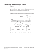
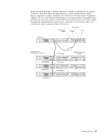
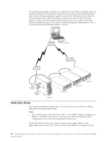
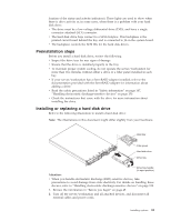
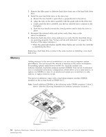
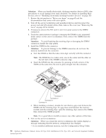
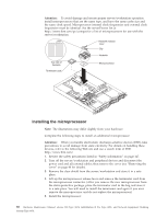
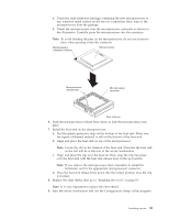
Memory 3. Remove the filler panel or defective hard drive from one of the hard disk drive bays. 4. Install the new hard disk drive in the drive bay: a. Ensure the tray handle is open (that is, perpendicular to the drive). b. Align the rails on the drive assembly with the guide rails in the drive bay. c. Gently push the drive assembly into the bay until the drive connects to the backplane. d. Push the tray handle toward the closed position until it locks the drive in place. 5. Reconnect the external cables and power cords; then, turn on the server/workstation. 6. Check the hard disk drive status indicators to verify that the hard disk drives are operating properly. (See "Server controls and indicators" on page 6 for the location of the status indicators.) v When the green light flashes rapidly (three flashes per second), the controller is identifying the drive. Replacing a hard disk drive is done in the same manner as installing a new hard disk drive. Adding memory to the server/workstation is an easy way to improve system performance. You can increase the amount of memory in the server/workstation by installing options called memory-module kits. Each kit contains one industry-standard, dual-inline memory module (DIMM). Your server/workstation uses a noninterleaved memory configuration, which allows you to add, remove, or replace one DIMM at a time. In an interleaved system you would have to add, remove, or replace memory in sets. The server/workstation comes with a dual inline memory module (DIMM) installed on the system board in DIMM slot 1. Note: Install additional DIMMs in the following order: DIMM connector 2, then 3, then 4. (See the following illustration for memory connector locations.) Connector 1 Connector 2 Connector 3 Connector 4 84 Hardware Maintenance Manual: xSeries 330 Type 8674, IntelliStation R Pro Type 6851, and Network Equipment Building System Type 8674
-
 1
1 -
2
-
3
-
4
-
5
-
6
-
7
-
8
-
9
-
10
-
11
-
12
-
13
-
14
-
15
-
16
-
17
-
18
-
19
-
20
-
21
-
22
-
23
-
24
-
25
-
26
-
27
-
28
-
29
-
30
-
31
-
32
-
33
-
34
-
35
-
36
-
37
-
38
-
39
-
40
-
41
-
42
-
43
-
44
-
45
-
46
-
47
-
48
-
49
-
50
-
51
-
52
-
53
-
54
-
55
-
56
-
57
-
58
-
59
-
60
-
61
-
62
-
63
-
64
-
65
-
66
-
67
-
68
-
69
-
70
-
71
-
72
-
73
-
74
-
75
-
76
-
77
-
78
-
79
-
80
-
81
-
82
-
83
-
84
-
85
-
86
-
 87
87 -
 88
88 -
 89
89 -
 90
90 -
 91
91 -
 92
92 -
 93
93 -
 94
94 -
 95
95 -
 96
96 -
 97
97 -
98
-
99
-
100
-
101
-
102
-
103
-
104
-
105
-
106
-
107
-
108
-
109
-
110
-
111
-
112
-
113
-
114
-
115
-
116
-
117
-
118
-
119
-
120
-
121
-
122
-
123
-
124
-
125
-
126
-
127
-
128
-
129
-
130
-
131
-
132
-
133
-
134
-
135
-
136
-
137
-
138
-
139
-
140
-
141
-
142
-
143
-
144
-
145
-
146
-
147
-
148
-
149
-
150
-
151
-
152
-
153
-
154
-
155
-
156
-
157
-
158
-
159
-
160
-
161
-
162
-
163
-
164
-
165
-
166
-
167
-
168
-
169
-
170
-
171
-
172
-
173
-
174
-
175
-
176
-
177
-
178
-
179
-
180
-
181
-
182
-
183
-
184
-
185
-
186
-
187
-
188
-
189
-
190
-
191
-
192
 |
 |