IBM 867431X Hardware Maintenance Manual - Page 105
Serial-port connector, Universal Serial Bus ports, USB cables and hubs, Save Settings, Exit Setup
 |
View all IBM 867431X manuals
Add to My Manuals
Save this manual to your list of manuals |
Page 105 highlights
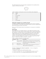
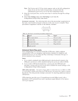
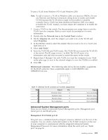
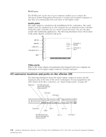
Note: The Devices and I/O Ports choice appears only on the full configuration menu. If you set two levels of passwords, you must enter the administrator password to access the full configuration menu. 4. Select the serial port; then, use the arrow keys to advance through the settings available. 5. Select Save Settings; then select Exit Setup to exit from the Configuration/Setup Utility main menu. Serial-port connector: The following table shows the pin-number assignments for the 9-pin, male D-shell serial-port connector on the rear of your computer. These pin-number assignments conform to the industry standard. 1 5 6 9 Table 15. Serial-port connectors pin-number assignments Pin Signal Pin 1 Data carrier detect 6 2 Receive data 7 3 Transmit data 8 4 Data terminal ready 9 5 Signal ground Signal Data set ready Request to send Clear to send Ring indicator Universal Serial Bus ports Your computer has two Universal Serial Bus (USB) ports, which configure automatically. USB is an emerging serial interface standard for telephony and multimedia devices. It uses Plug and Play technology to determine the type of device attached to the connector. Notes: 1. If you attach a standard (non-USB) keyboard to the keyboard connector, the USB ports and devices will be disabled during the power-on self-test (POST). 2. If you install a USB keyboard that has a mouse port, the USB keyboard emulates a mouse and you will not be able to disable the mouse settings in the Configuration/Setup Utility program. USB cables and hubs: You need a 4-pin cable to connect devices to USB 1 or USB 2. If you plan to attach more than two USB devices, you must use a hub to connect the devices. The hub provides multiple connectors for attaching additional external USB devices. USB technology provides up to 12 megabits-per-second (Mbps) speed with a maximum of 127 external devices and a maximum signal distance of five meters (16 ft). per segment. Installing options 97
-
 1
1 -
2
-
3
-
4
-
5
-
6
-
7
-
8
-
9
-
10
-
11
-
12
-
13
-
14
-
15
-
16
-
17
-
18
-
19
-
20
-
21
-
22
-
23
-
24
-
25
-
26
-
27
-
28
-
29
-
30
-
31
-
32
-
33
-
34
-
35
-
36
-
37
-
38
-
39
-
40
-
41
-
42
-
43
-
44
-
45
-
46
-
47
-
48
-
49
-
50
-
51
-
52
-
53
-
54
-
55
-
56
-
57
-
58
-
59
-
60
-
61
-
62
-
63
-
64
-
65
-
66
-
67
-
68
-
69
-
70
-
71
-
72
-
73
-
74
-
75
-
76
-
77
-
78
-
79
-
80
-
81
-
82
-
83
-
84
-
85
-
86
-
87
-
88
-
89
-
90
-
91
-
92
-
93
-
94
-
95
-
96
-
97
-
98
-
99
-
 100
100 -
 101
101 -
 102
102 -
 103
103 -
 104
104 -
 105
105 -
 106
106 -
 107
107 -
 108
108 -
 109
109 -
 110
110 -
111
-
112
-
113
-
114
-
115
-
116
-
117
-
118
-
119
-
120
-
121
-
122
-
123
-
124
-
125
-
126
-
127
-
128
-
129
-
130
-
131
-
132
-
133
-
134
-
135
-
136
-
137
-
138
-
139
-
140
-
141
-
142
-
143
-
144
-
145
-
146
-
147
-
148
-
149
-
150
-
151
-
152
-
153
-
154
-
155
-
156
-
157
-
158
-
159
-
160
-
161
-
162
-
163
-
164
-
165
-
166
-
167
-
168
-
169
-
170
-
171
-
172
-
173
-
174
-
175
-
176
-
177
-
178
-
179
-
180
-
181
-
182
-
183
-
184
-
185
-
186
-
187
-
188
-
189
-
190
-
191
-
192
 |
 |
