IBM 867431X Hardware Maintenance Manual - Page 14
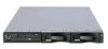
Server controls and indicators, Front view, Power-control button, Power-on light, Reset button
 |
View all IBM 867431X manuals
Add to My Manuals
Save this manual to your list of manuals |
Page 14 highlights
v Predictive Failure Alerts (PFA) v Remote system problem-analysis support v Power and temperature monitoring v Hot-swap drive bays v Error codes and messages v System error logging v Upgradable BIOS, diagnostics, and Advanced System Management Processor code v Automatic restart after a power failure v Parity checking on the PCI buses v CRC checking on the SCSI buses v Error checking and correcting (ECC) memory v Redundant Ethernet capabilities v Light Path Diagnostics on the system board v Vital Product Data (VPD) on system board, and SCSI backplane Server controls and indicators This section identifies the controls and indicators on the front and the back of your server. Front view Power control button Power-on light (green) Reset button Select button/indicator (green) System error light (amber) Diskette drive activity light (green) Hard disk drive status light (amber) Diskette eject button CD activity light (green) CD eject button Hard disk drive activity light (green) Power-control button: Press this button to manually turn the server on or off. Power-on light: This green LED lights and stays on when you turn on your server and blinks when the server is in standby mode. Reset button: Press this button to reset the server and run the power-on self-test (POST). You might need to use a pen or the end of a straightened paper clip to press the button. Select button/indicator: Press this button to select the server in the C2T chain. The green LED on this button lights when the monitor, keyboard, and mouse are logically connected to this server. System-error light: This amber LED lights when a system error occurs. An LED on the Light Path Diagnostic panel on the system board will also be on to further isolate the error. Diskette drive activity light: When this LED is on, it indicates that the diskette drive is in use. 6 Hardware Maintenance Manual: xSeries 330 Type 8674, IntelliStation R Pro Type 6851, and Network Equipment Building System Type 8674
-
 1
1 -
2
-
3
-
4
-
5
-
6
-
7
-
8
-
 9
9 -
 10
10 -
 11
11 -
 12
12 -
 13
13 -
 14
14 -
 15
15 -
 16
16 -
 17
17 -
 18
18 -
 19
19 -
20
-
21
-
22
-
23
-
24
-
25
-
26
-
27
-
28
-
29
-
30
-
31
-
32
-
33
-
34
-
35
-
36
-
37
-
38
-
39
-
40
-
41
-
42
-
43
-
44
-
45
-
46
-
47
-
48
-
49
-
50
-
51
-
52
-
53
-
54
-
55
-
56
-
57
-
58
-
59
-
60
-
61
-
62
-
63
-
64
-
65
-
66
-
67
-
68
-
69
-
70
-
71
-
72
-
73
-
74
-
75
-
76
-
77
-
78
-
79
-
80
-
81
-
82
-
83
-
84
-
85
-
86
-
87
-
88
-
89
-
90
-
91
-
92
-
93
-
94
-
95
-
96
-
97
-
98
-
99
-
100
-
101
-
102
-
103
-
104
-
105
-
106
-
107
-
108
-
109
-
110
-
111
-
112
-
113
-
114
-
115
-
116
-
117
-
118
-
119
-
120
-
121
-
122
-
123
-
124
-
125
-
126
-
127
-
128
-
129
-
130
-
131
-
132
-
133
-
134
-
135
-
136
-
137
-
138
-
139
-
140
-
141
-
142
-
143
-
144
-
145
-
146
-
147
-
148
-
149
-
150
-
151
-
152
-
153
-
154
-
155
-
156
-
157
-
158
-
159
-
160
-
161
-
162
-
163
-
164
-
165
-
166
-
167
-
168
-
169
-
170
-
171
-
172
-
173
-
174
-
175
-
176
-
177
-
178
-
179
-
180
-
181
-
182
-
183
-
184
-
185
-
186
-
187
-
188
-
189
-
190
-
191
-
192
 |
 |
