Intel SR1530HCLRNA User Guide - Page 79
Routing Data and Power Cables to Optical Drive SR1530HCL, SR1530HCLS and SR1530HCLR/
 |
UPC - 735858197274
View all Intel SR1530HCLRNA manuals
Add to My Manuals
Save this manual to your list of manuals |
Page 79 highlights
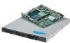
9. Connect the power cable to the power connector on the optical drive. Connect the data cable between the connector on the optical drive and the IDE connector on the server board. A B B A AF001647 Figure 55. Routing Data and Power Cables to Optical Drive (SR1530HCL/ SR1530HCLS and SR1530HCLR/SR1530HCLSR) 10. Install the server system cover. For instructions, see "Installing the Server System Cover" on page 30. 11. Optional: Install the front bezel. For instructions, see "Installing the Front Bezel" on page 27. 12. Plug all peripheral devices and the AC power cable into the server. Server System User Guide 57
-
 1
1 -
2
-
3
-
4
-
5
-
6
-
7
-
8
-
9
-
10
-
11
-
12
-
13
-
14
-
15
-
16
-
17
-
18
-
19
-
20
-
21
-
22
-
23
-
24
-
25
-
26
-
27
-
28
-
29
-
30
-
31
-
32
-
33
-
34
-
35
-
36
-
37
-
38
-
39
-
40
-
41
-
42
-
43
-
44
-
45
-
46
-
47
-
48
-
49
-
50
-
51
-
52
-
53
-
54
-
55
-
56
-
57
-
58
-
59
-
60
-
61
-
62
-
63
-
64
-
65
-
66
-
67
-
68
-
69
-
70
-
71
-
72
-
73
-
 74
74 -
 75
75 -
 76
76 -
 77
77 -
 78
78 -
 79
79 -
 80
80 -
 81
81 -
 82
82 -
 83
83 -
 84
84 -
85
-
86
-
87
-
88
-
89
-
90
-
91
-
92
-
93
-
94
-
95
-
96
-
97
-
98
-
99
-
100
-
101
-
102
-
103
-
104
-
105
-
106
-
107
-
108
-
109
-
110
-
111
-
112
-
113
-
114
-
115
-
116
-
117
-
118
-
119
-
120
-
121
-
122
-
123
-
124
-
125
-
126
-
127
-
128
-
129
-
130
-
131
-
132
-
133
-
134
-
135
-
136
-
137
-
138
-
139
-
140
-
141
-
142
-
143
-
144
-
145
-
146
-
147
-
148
-
149
-
150
-
151
-
152
-
153
-
154
-
155
-
156
-
157
-
158
-
159
-
160
-
161
-
162
-
163
-
164
-
165
-
166
-
167
-
168
-
169
-
170
-
171
-
172
-
173
-
174
-
175
-
176
-
177
-
178
-
179
-
180
-
181
-
182
-
183
-
184
-
185
-
186
-
187
-
188
-
189
-
190
-
191
-
192
-
193
-
194
 |
 |

Server System User Guide
57
9.
Connect the power cable to the power connector on the optical drive. Connect the
data cable between the connector on the optical drive and the IDE connector on the
server board.
Figure 55. Routing Data and Power Cables to Optical Drive (SR1530HCL/
SR1530HCLS and SR1530HCLR/SR1530HCLSR)
10.
Install the server system cover. For instructions, see
“Installing the Server System
Cover” on page 30
.
11.
Optional: Install the front bezel. For instructions, see
“Installing the Front Bezel”
on page 27
.
12.
Plug all peripheral devices and the AC power cable into the server.
B
A
B
A
AF001647