Invacare SOLARA3G Owners Manual - Page 103
Contracture Foot Assembly
 |
View all Invacare SOLARA3G manuals
Add to My Manuals
Save this manual to your list of manuals |
Page 103 highlights
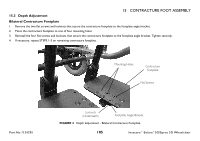
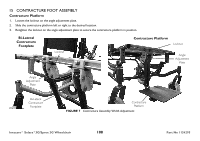
15 CONTRACTURE FOOT ASSEMBLY 15.2 Adjusting the Angle of the Bilateral Contracture Footplate Adjusting the Side to Side Angle 1. Loosen the adjustment screw located underneath the contracture footplate. See Detail "A". 2. Tilt the contracture footplate left or right to the desired angle. See Detail "B". 3. Retighten the adjustment screw. 4. If necessary, repeat STEPS 1-3 on remaining contracture footplate. DETAIL "A" DETAIL "B" Contracture Footplate Part No 1154295 Adjustment Screw Contracture Footplate Adjustment Screw FIGURE 2 Adjusting the Angle of the Contracture Assembly 103 Invacare® Solara®3G/Spree 3G Wheelchair
-
 1
1 -
2
-
3
-
4
-
5
-
6
-
7
-
8
-
9
-
10
-
11
-
12
-
13
-
14
-
15
-
16
-
17
-
18
-
19
-
20
-
21
-
22
-
23
-
24
-
25
-
26
-
27
-
28
-
29
-
30
-
31
-
32
-
33
-
34
-
35
-
36
-
37
-
38
-
39
-
40
-
41
-
42
-
43
-
44
-
45
-
46
-
47
-
48
-
49
-
50
-
51
-
52
-
53
-
54
-
55
-
56
-
57
-
58
-
59
-
60
-
61
-
62
-
63
-
64
-
65
-
66
-
67
-
68
-
69
-
70
-
71
-
72
-
73
-
74
-
75
-
76
-
77
-
78
-
79
-
80
-
81
-
82
-
83
-
84
-
85
-
86
-
87
-
88
-
89
-
90
-
91
-
92
-
93
-
94
-
95
-
96
-
97
-
 98
98 -
 99
99 -
 100
100 -
 101
101 -
 102
102 -
 103
103 -
 104
104 -
 105
105 -
 106
106 -
 107
107 -
 108
108 -
109
-
110
-
111
-
112
-
113
-
114
-
115
-
116
-
117
-
118
-
119
-
120
-
121
-
122
-
123
-
124
 |
 |

15
CONTRACTURE FOOT ASSEMBLY
Part No 1154295
103
Invacare® Solara®3G/Spree 3G Wheelchair
15.2
Adjusting the Angle of the Bilateral Contracture Footplate
Adjusting the Side to Side Angle
1.
Loosen the adjustment screw located underneath the contracture footplate. See Detail “A”.
2.
Tilt the contracture footplate left or right to the desired angle. See Detail “B”.
3.
Retighten the adjustment screw.
4.
If necessary, repeat STEPS 1-3 on remaining contracture footplate.
FIGURE 2
Adjusting the Angle of the Contracture Assembly
DETAIL “A”
Contracture
Footplate
Adjustment
Screw
DETAIL “B”
Contracture
Footplate
Adjustment
Screw