Invacare SOLARA3G Owners Manual - Page 90
Detail A, Detail B
 |
View all Invacare SOLARA3G manuals
Add to My Manuals
Save this manual to your list of manuals |
Page 90 highlights
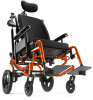
13 WHEEL LOCKS/ANTI-TIPPERS B. Slide the wheel lock bracket along the wheelchair frame until the measurement between the wheel lock shoe and rear wheel is approximately 1.25 inches. C. Secure the foot lock lever to the connecting wheel lock link in the corresponding adjustment hole. D. Repeat STEPS 3 for remaining wheel lock bracket. 4. Tighten the four mounting screws to 50 inch pounds. 5. Engage the footlock and push against the wheelchair to determine if the footlock engages the rear wheels enough to hold the wheelchair. 6. Repeat STEPS 1-5 until the footlock engages the rear wheels enough to hold the wheelchair. DETAIL "A" Foot Lock Lever DETAIL "B" Locknut Washers Wheelchair Frame Mounting Screws Wheel Lock Bracket Wheel Lock Shoe Rear Wheel Mounting Screw Adjustment Holes Connecting Wheel Lock Link FIGURE 2 Wheel Lock Adjustment - Footlock Invacare® Solara®3G/Spree 3G Wheelchair 90 Part No 1154295
-
 1
1 -
2
-
3
-
4
-
5
-
6
-
7
-
8
-
9
-
10
-
11
-
12
-
13
-
14
-
15
-
16
-
17
-
18
-
19
-
20
-
21
-
22
-
23
-
24
-
25
-
26
-
27
-
28
-
29
-
30
-
31
-
32
-
33
-
34
-
35
-
36
-
37
-
38
-
39
-
40
-
41
-
42
-
43
-
44
-
45
-
46
-
47
-
48
-
49
-
50
-
51
-
52
-
53
-
54
-
55
-
56
-
57
-
58
-
59
-
60
-
61
-
62
-
63
-
64
-
65
-
66
-
67
-
68
-
69
-
70
-
71
-
72
-
73
-
74
-
75
-
76
-
77
-
78
-
79
-
80
-
81
-
82
-
83
-
84
-
 85
85 -
 86
86 -
 87
87 -
 88
88 -
 89
89 -
 90
90 -
 91
91 -
 92
92 -
 93
93 -
 94
94 -
 95
95 -
96
-
97
-
98
-
99
-
100
-
101
-
102
-
103
-
104
-
105
-
106
-
107
-
108
-
109
-
110
-
111
-
112
-
113
-
114
-
115
-
116
-
117
-
118
-
119
-
120
-
121
-
122
-
123
-
124
 |
 |
