Invacare SOLARA3G Owners Manual - Page 65
Invacare SOLARA3G Manual
 |
View all Invacare SOLARA3G manuals
Add to My Manuals
Save this manual to your list of manuals |
Page 65 highlights
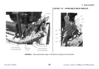
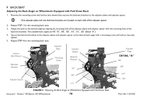
Adjusting Non-Locking Cantilever Arm Height 1. Remove the locknut and washer from the lower hex bolt securing the cantilever arm to the back cane. 2. Slide the cantilever arm assembly out of the back cane. 3. Reposition the cantilever arm assembly to the desired mounting hole. 4. Secure the cantilever arm to the wheelchair with a washer and locknut. Adjusting Non-Locking Cantilever Arm Angle 1. Loosen the mounting screw securing the cam to the cantilever arm. 2. Rotate the cam until the desired angle is achieved (Detail "A"). 3. Tighten the mounting screw securing the cam to the cantilever arm. Side View of Cam Cam Back Cane Mounting Screw 8 ARMS Back Cane Cantilever Arm Cantilever Arm DETAIL "A" CAM POSITIONS NOTE: All arm angles are relative to the back cane. 0° Arm Angle 4° Arm Angle Back Cane Cam 8° Arm Angle 12° Arm Angle 16° Arm Angle Part No 1154295 FIGURE 15 Adjusting Non-Locking Cantilever Arm Angle 65 Invacare® Solara®3G/Spree 3G Wheelchair
-
 1
1 -
2
-
3
-
4
-
5
-
6
-
7
-
8
-
9
-
10
-
11
-
12
-
13
-
14
-
15
-
16
-
17
-
18
-
19
-
20
-
21
-
22
-
23
-
24
-
25
-
26
-
27
-
28
-
29
-
30
-
31
-
32
-
33
-
34
-
35
-
36
-
37
-
38
-
39
-
40
-
41
-
42
-
43
-
44
-
45
-
46
-
47
-
48
-
49
-
50
-
51
-
52
-
53
-
54
-
55
-
56
-
57
-
58
-
59
-
 60
60 -
 61
61 -
 62
62 -
 63
63 -
 64
64 -
 65
65 -
 66
66 -
 67
67 -
 68
68 -
 69
69 -
 70
70 -
71
-
72
-
73
-
74
-
75
-
76
-
77
-
78
-
79
-
80
-
81
-
82
-
83
-
84
-
85
-
86
-
87
-
88
-
89
-
90
-
91
-
92
-
93
-
94
-
95
-
96
-
97
-
98
-
99
-
100
-
101
-
102
-
103
-
104
-
105
-
106
-
107
-
108
-
109
-
110
-
111
-
112
-
113
-
114
-
115
-
116
-
117
-
118
-
119
-
120
-
121
-
122
-
123
-
124
 |
 |
