Kenmore HE2t User Guide - Page 14
Installation Instructions - inlet valve
 |
View all Kenmore HE2t manuals
Add to My Manuals
Save this manual to your list of manuals |
Page 14 highlights
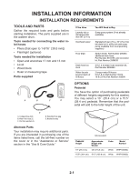
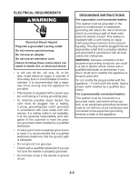
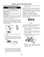
INSTALLATION INSTRUCTIONS REMOVE TRANSPORT SYSTEM 4. Close the bolt holes with the 4 transport bolt hole plugs. Excessive Weight Hazard Use two or more people to move and install washer. Failure to do so can result in back or other injury. IMPORTANT: Position the washer so that the rear of the unit is within approximately 3 ft (90 cm) of the final location. NOTE: If the washer is to be transported at a later date, call your local service center. To avoid suspension and structural damage, your machine must be properly set up for relocation by a certified technician. CONNECT THE INLET HOSES Insert new flat washers (supplied) into each end of the inlet hoses. Firmly seat the washers in the couplings. There are 4 bolts in the rear panel of the washer that support the suspension system during transportation. These bolts also retain the power cord inside the washer until the bolts are removed. A B A. Coupling B. Washer Connect the inlet hoses to the water faucets Make sure the washer drum is empty. 1. Attach a hose to the hot water faucet. Screw on coupling by hand until it is seated on the washer. 1. Using a 13 mm wrench, loosen each of the bolts. 2. Once the bolt is loose, move it to the center of the hole and completely pull out the bolt, including the plastic spacer covering the bolt. 2. Attach a hose to the cold water faucet. Screw on coupling by hand until it is seated on the washer. 3. Using pliers, tighten the couplings with an additional two-thirds turn. 3. Once all 4 bolts are removed, discard the bolts and spacers. Then pull the power cord through the opening of the rear panel and close the hole with the attached cap. 2-6 NOTE: Do not overtighten or use tape or sealants on the valve. Damage to the valves can result.
-
 1
1 -
2
-
3
-
4
-
5
-
6
-
7
-
8
-
 9
9 -
 10
10 -
 11
11 -
 12
12 -
 13
13 -
 14
14 -
 15
15 -
 16
16 -
 17
17 -
 18
18 -
 19
19 -
20
-
21
-
22
-
23
-
24
-
25
-
26
-
27
-
28
-
29
-
30
-
31
-
32
-
33
-
34
-
35
-
36
-
37
-
38
-
39
-
40
-
41
-
42
-
43
-
44
-
45
-
46
-
47
-
48
-
49
-
50
-
51
-
52
-
53
-
54
-
55
-
56
-
57
-
58
-
59
-
60
-
61
-
62
-
63
-
64
-
65
-
66
-
67
-
68
-
69
-
70
-
71
-
72
-
73
-
74
-
75
-
76
-
77
-
78
-
79
-
80
-
81
-
82
-
83
-
84
-
85
-
86
-
87
-
88
-
89
-
90
-
91
-
92
-
93
-
94
-
95
-
96
 |
 |
