Kenmore HE2t User Guide - Page 81
Display, Explanation And Recommended Procedure - service manual
 |
View all Kenmore HE2t manuals
Add to My Manuals
Save this manual to your list of manuals |
Page 81 highlights
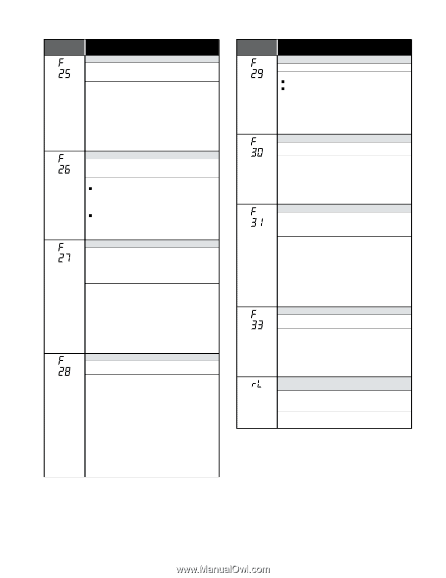
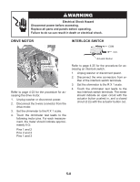
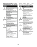
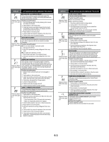
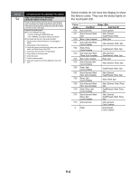
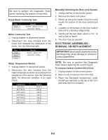
DISPLAY EXPLANATION AND RECOMMENDED PROCEDURE Reference Status LEDs chart, page 6-4 DRIVE MOTOR TACHOMETER ERROR If the control is unable to properly detect motor speed, the machine shuts down. If a failure occurs during high-speed spin, the door unlocks after 3 minutes. Possible Causes/Procedure 1. Verify the shipping system including shipping bolts, spacers and cables are removed. 2. Unplug washer or disconnect power. 3. Check wire harness connections between the drive motor and the Motor Control Unit (MCU), and between the MCU and the Central Control Unit (CCU). 4. Plug in washer or reconnect power. 5. Check the MCU by looking for operations of the drive motor. 6. Check the drive motor for powered rotations. Reference Status LEDs chart, page 6-4 Reference Status LEDs chart, page 6-4 DOOR SWITCH ERROR If the door has not been opened for 3 consecutive cycles or the door switch is open while the door is locked for more than 5 seconds. Possible Causes/Procedure Door not opened during 3 consecutive cycles. 1. Open and close the door. 2. Verify CCU operation by running a Diagnostic Test or any cycle. Door switch open while door is locked. 1. Push the door and check if it is completely closed. 2. Verify CCU operation by running a Diagnostic Test or any cycle. OVERFLOW CONDITION If the overflow contact on the pressure switch is closed for more than 60 seconds, an Overflow Condition occurs. In an overflow condition, the door remains locked and the drain pump runs constantly, even if PAUSE/CANCEL is pressed twice and the display is cleared. Turn off hot and cold water faucets and unplug the unit before servicing. Possible Causes/Procedure 1. Check the drain hose and make sure it is not plugged or kinked. 2. Unplug washer or disconnect power. 3. Check wire harness connections to the drain pump, pressure switch, water inlet value, and Central Control Unit (CCU). 4. Check/clean drain pump filter of foreign objects. 5. Check for drain pump failure. 6. Check the inlet valve for proper shut off. 7. Check the pressure switch for proper operation. Reference Status LEDs chart, page 6-4 SERIAL COMMUNICATION ERROR The communication between the Central Control Unit (CCU) and the Motor Control Unit (MCU) cannot be sent correctly. Possible Causes/Procedure 1. Unplug washer or disconnect power. 2. Check wire harness connections to the MCU, the motor, and Central Control Unit (CCU). - Check connections of the CCU board within the housing. - Make sure all grounding switches are engaged. 3. Check the drive system for any worn or failed components. 4. Plug in washer or reconnect power. 5. Verify CCU operation by running a Diagnostic Test or any cycle. 6. Check the MCU by looking for operations of the drive motor. 7. Check the drive motor for powered rotations. 8. Check that the serial harness at the MCU is not mounted upside down. The wires should be to the left when facing the MCU connectors. DISPLAY EXPLANATION AND RECOMMENDED PROCEDURE Reference Status LEDs chart, page 6-4 Reference Status LEDs chart, page 6-4 Reference Status LEDs chart, page 6-4 Reference Status LEDs chart, page 6-4 Reference Status LEDs chart, page 6-4 DOOR UNLOCK ERROR If the door unlock has failed 6 times. Possible Causes/Procedure Door lock mechanism is broken. Door switch/lock unit failure. 1. Check door switch/lock unit for foreign objects. 2. Unplug washer or disconnect power. 3. Check wire harness connections to the door switch/lock unit and Central Control Unit (CCU). NOTE: The door switch/lock unit can be manually unlocked. See Manually Unlocking The Door Lock System. DISPENSER SYSTEM ERROR When the dispenser motor cannot be driven to its proper position. Possible Causes/Procedure 1. Unplug washer or disconnect power. 2. Check mechanical linkage from dispenser motor to the top of the dispenser. 3. Check wire harness connections to the dispenser motor and Central Control Unit (CCU). 4. Check dispenser motor for powered rotations. MCU FAILURE If the heat sink gets too hot, the Motor Control Unit (MCU) will stop the motor, the MCU will communicate this failure to the Central Control Unit (CCU), then the CCU will reset the MCU. If the condition continues four times, the F31 code will show. Possible Causes/Procedure 1. Check for proper installation, verify the unit is not located near a source of heat and has proper ventilation. 2. Unplug washer or disconnect power. 3. Check wire harness connections to the MCU, the motor, and Central Control Unit (CCU). 4. Check the drive system for any worn or failed components. 5. Plug in washer or reconnect power. 6. Check the MCU by looking for operations of the drive motor. 7. Check the drive motor for powered rotations. PUMP DRIVE SYSTEM ERROR When the connection between pump and the Central Control Unit (CCU) is lost. Possible Causes/Procedure 1. Unplug washer or disconnect power. 2. Check wire harness connections to the pump and Central Control Unit (CCU). 3. Plug in washer or reconnect power. 4. Verify CCU operation by running a Diagnostic Test or any cycle. Refer to the Continuity tests. LOAD INSIDE DRUM DURING CLEANING WASHER CYCLE If at the start of the CLEANING WASHER cycle a load is detected inside the drum. NOTE: Detects by weight. Possible Causes/Procedure Remove clothes from drum and start the cycle again. 6-3
-
 1
1 -
2
-
3
-
4
-
5
-
6
-
7
-
8
-
9
-
10
-
11
-
12
-
13
-
14
-
15
-
16
-
17
-
18
-
19
-
20
-
21
-
22
-
23
-
24
-
25
-
26
-
27
-
28
-
29
-
30
-
31
-
32
-
33
-
34
-
35
-
36
-
37
-
38
-
39
-
40
-
41
-
42
-
43
-
44
-
45
-
46
-
47
-
48
-
49
-
50
-
51
-
52
-
53
-
54
-
55
-
56
-
57
-
58
-
59
-
60
-
61
-
62
-
63
-
64
-
65
-
66
-
67
-
68
-
69
-
70
-
71
-
72
-
73
-
74
-
75
-
 76
76 -
 77
77 -
 78
78 -
 79
79 -
 80
80 -
 81
81 -
 82
82 -
 83
83 -
 84
84 -
 85
85 -
 86
86 -
87
-
88
-
89
-
90
-
91
-
92
-
93
-
94
-
95
-
96
 |
 |