Kenmore HE2t User Guide - Page 71
Component Testing
 |
View all Kenmore HE2t manuals
Add to My Manuals
Save this manual to your list of manuals |
Page 71 highlights
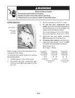
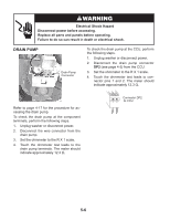
COMPONENT TESTING Before testing any of the components, perform the following checks: • Control failure can be the result of corrosion on connectors. Therefore, disconnecting and reconnecting wires will be necessary throughout test procedures. • All tests/checks should be made with a VOM or DVM having a sensitivity of 20,000 ohms-per-volt DC, or greater. • Check all connections before replacing components, looking for broken or loose wires, failed terminals, or wires not pressed into connectors far enough. • Resistance checks must be made with power cord unplugged from outlet, and with wiring harness or connectors disconnected. • Unless stated otherwise, make all resistance checks by disconnecting the component connector at the Central Control Unit (CCU). Electrical Shock Hazard Disconnect power before accessing. Replace all parts and panels before operating. Failure to do so can result in death or electrical shock. INLET VALVE SOLENOIDS COLD HOT Refer to page 4-6 for the procedure for accessing the inlet valve. To check the inlet valve solenoids at the component terminals, perform the following steps. 1. Unplug washer or disconnect power. 2. Disconnect the solenoid connectors from the inlet valve terminals. 3. Set the ohmmeter to the R X 100 scale. 4. Touch the ohmmeter test leads to the cold and hot water connector terminals. The meter should indicate between 750 and 850 Ω. To check the inlet valve solenoids at the CCU, perform the following steps. 1. Unplug washer or disconnect power. 2. Disconnect the inlet valve solenoid connector VCH7 (see page 4-5) from the CCU. 3. Set the ohmmeter to the R X 100 scale. 4. Touch the ohmmeter test leads to the following connector pins. The meter should indicate between 750 and 850 Ω. • Pins 1 & 3 (cold) • Pins 5 & 7 (hot) 1 2 3 4 5 6 7 Connector VCH7 At CCU COLD HOT 5-1
-
 1
1 -
2
-
3
-
4
-
5
-
6
-
7
-
8
-
9
-
10
-
11
-
12
-
13
-
14
-
15
-
16
-
17
-
18
-
19
-
20
-
21
-
22
-
23
-
24
-
25
-
26
-
27
-
28
-
29
-
30
-
31
-
32
-
33
-
34
-
35
-
36
-
37
-
38
-
39
-
40
-
41
-
42
-
43
-
44
-
45
-
46
-
47
-
48
-
49
-
50
-
51
-
52
-
53
-
54
-
55
-
56
-
57
-
58
-
59
-
60
-
61
-
62
-
63
-
64
-
65
-
 66
66 -
 67
67 -
 68
68 -
 69
69 -
 70
70 -
 71
71 -
 72
72 -
 73
73 -
 74
74 -
 75
75 -
 76
76 -
77
-
78
-
79
-
80
-
81
-
82
-
83
-
84
-
85
-
86
-
87
-
88
-
89
-
90
-
91
-
92
-
93
-
94
-
95
-
96
 |
 |
