Lenovo NetVista Hardware Maintenance Manual (HMM) for NetVista 6832 and 6833 s - Page 146
IBM Desktop System HMM, The white corner of the jumper block, represents pin 1.
 |
View all Lenovo NetVista manuals
Add to My Manuals
Save this manual to your list of manuals |
Page 146 highlights
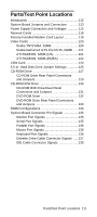
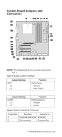
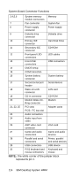
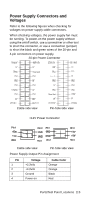
System Board Connector Functions 3,4,5,6 System memory Memory module connectors 7 Fan connector System fan 8 Power supply Power supply connector 9 Diskette drive Diskette drive connector 10 Primary IDE Hard Disk Drive connector 11 Secondary IDE CD-ROM connector 12 Front panel LED LED cables connectors 13 Front USB USB connectors connectors 14 CMOS setup 15 COM2 detection 16 System battery System battery connector 17 Second serial port Serial devices header 18 Wake-on-LAN LAN card connector 19 CD-in connector CD-ROM 20 Modem Wake-On- Modem Ring connector 21, 22, 25 PCI slots PCI3: I2C bus slot Adapter cards 23 Audio connectors 24 Audio input from video 26 AGP video card VGA card connector 27 Game and audio Game and audio connectors devices 28 Parallel and serial Printer, parallel connectors and serial devices 29 USB connectors USB device 30 PS/2 keyboard and Keyboard and mouse connectors mouse NOTE: The white corner of the jumper block represents pin 1. 114 IBM Desktop System HMM
-
 1
1 -
2
-
3
-
4
-
5
-
6
-
7
-
8
-
9
-
10
-
11
-
12
-
13
-
14
-
15
-
16
-
17
-
18
-
19
-
20
-
21
-
22
-
23
-
24
-
25
-
26
-
27
-
28
-
29
-
30
-
31
-
32
-
33
-
34
-
35
-
36
-
37
-
38
-
39
-
40
-
41
-
42
-
43
-
44
-
45
-
46
-
47
-
48
-
49
-
50
-
51
-
52
-
53
-
54
-
55
-
56
-
57
-
58
-
59
-
60
-
61
-
62
-
63
-
64
-
65
-
66
-
67
-
68
-
69
-
70
-
71
-
72
-
73
-
74
-
75
-
76
-
77
-
78
-
79
-
80
-
81
-
82
-
83
-
84
-
85
-
86
-
87
-
88
-
89
-
90
-
91
-
92
-
93
-
94
-
95
-
96
-
97
-
98
-
99
-
100
-
101
-
102
-
103
-
104
-
105
-
106
-
107
-
108
-
109
-
110
-
111
-
112
-
113
-
114
-
115
-
116
-
117
-
118
-
119
-
120
-
121
-
122
-
123
-
124
-
125
-
126
-
127
-
128
-
129
-
130
-
131
-
132
-
133
-
134
-
135
-
136
-
137
-
138
-
139
-
140
-
 141
141 -
 142
142 -
 143
143 -
 144
144 -
 145
145 -
 146
146 -
 147
147 -
 148
148 -
 149
149 -
 150
150 -
 151
151 -
152
-
153
-
154
-
155
-
156
-
157
-
158
-
159
-
160
-
161
-
162
-
163
-
164
-
165
-
166
-
167
-
168
-
169
-
170
-
171
-
172
-
173
-
174
-
175
-
176
-
177
-
178
-
179
-
180
-
181
-
182
-
183
-
184
-
185
-
186
-
187
-
188
-
189
-
190
-
191
-
192
-
193
-
194
-
195
-
196
-
197
-
198
-
199
-
200
-
201
-
202
-
203
-
204
-
205
-
206
-
207
-
208
-
209
-
210
-
211
 |
 |
