Lenovo ThinkStation P900 (English) User Guide - ThinkStation P900 (type 30A4 a - Page 135
Replacing the rear fan assembly, Notes, What to do next, Attention, CAUTION
 |
View all Lenovo ThinkStation P900 manuals
Add to My Manuals
Save this manual to your list of manuals |
Page 135 highlights
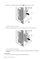
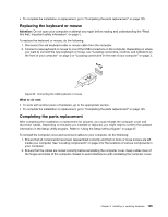
Notes: • You might have to gently twist the heat sink and fan assembly to free it from the microprocessor. • Do not touch the thermal grease while handling the heat sink and fan assembly. 9. To install the new heat sink and fan assembly, position the new heat sink and fan assembly on the system board so that the four screws are aligned with the holes on the system board. Note: Position the new heat sink and fan assembly so that the heat sink and fan assembly cable is toward the heat-sink-and-fan-assembly connector on the system board. 10. Follow the following sequence to install the four screws to secure the new heat sink and fan assembly. Do not over-tighten the screws. a. Partially tighten screw 1 , then fully tighten screw 2 , and then fully tighten screw 1 . b. Partially tighten screw 3 , then fully tighten screw 4 , and then fully tighten screw 3 . 11. Connect the cable of the new heat sink and fan assembly to the system board. See "Locating parts on the system board" on page 5. 12. Reinstall the direct cooling air baffle. See "Removing and reinstalling the direct cooling air baffle" on page 94. What to do next: • To work with another piece of hardware, go to the appropriate section. • To complete the installation or replacement, go to "Completing the parts replacement" on page 125. Replacing the rear fan assembly Attention: Do not open your computer or attempt any repair before reading and understanding the "Read this first: Important safety information" on page v. CAUTION: Hazardous moving parts. Keep fingers and other body parts away. To replace the rear fan assembly, do the following: 1. Remove all media from the drives and turn off all attached devices and the computer. Then, disconnect all power cords from electrical outlets and disconnect all cables that are connected to the computer. 2. Remove the computer cover. See "Removing the computer cover" on page 77. 3. Remove the direct cooling air baffle. See "Removing and reinstalling the direct cooling air baffle" on page 94. 4. Locate the rear fan assembly. See "Locating components" on page 4. Chapter 9. Installing or replacing hardware 123
-
 1
1 -
2
-
3
-
4
-
5
-
6
-
7
-
8
-
9
-
10
-
11
-
12
-
13
-
14
-
15
-
16
-
17
-
18
-
19
-
20
-
21
-
22
-
23
-
24
-
25
-
26
-
27
-
28
-
29
-
30
-
31
-
32
-
33
-
34
-
35
-
36
-
37
-
38
-
39
-
40
-
41
-
42
-
43
-
44
-
45
-
46
-
47
-
48
-
49
-
50
-
51
-
52
-
53
-
54
-
55
-
56
-
57
-
58
-
59
-
60
-
61
-
62
-
63
-
64
-
65
-
66
-
67
-
68
-
69
-
70
-
71
-
72
-
73
-
74
-
75
-
76
-
77
-
78
-
79
-
80
-
81
-
82
-
83
-
84
-
85
-
86
-
87
-
88
-
89
-
90
-
91
-
92
-
93
-
94
-
95
-
96
-
97
-
98
-
99
-
100
-
101
-
102
-
103
-
104
-
105
-
106
-
107
-
108
-
109
-
110
-
111
-
112
-
113
-
114
-
115
-
116
-
117
-
118
-
119
-
120
-
121
-
122
-
123
-
124
-
125
-
126
-
127
-
128
-
129
-
 130
130 -
 131
131 -
 132
132 -
 133
133 -
 134
134 -
 135
135 -
 136
136 -
 137
137 -
 138
138 -
 139
139 -
 140
140 -
141
-
142
-
143
-
144
-
145
-
146
-
147
-
148
-
149
-
150
-
151
-
152
-
153
-
154
-
155
-
156
-
157
-
158
-
159
-
160
-
161
-
162
-
163
-
164
 |
 |
