Lenovo ThinkStation P900 (English) User Guide - ThinkStation P900 (type 30A4 a - Page 18
System board part locations, Microprocessor fan connector 1
 |
View all Lenovo ThinkStation P900 manuals
Add to My Manuals
Save this manual to your list of manuals |
Page 18 highlights
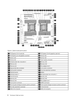
3 4 5 6 7 8 9 10 11 12 13 14 15 16 17 18 19 20 59 58 21 57 56 55 54 53 52 51 50 49 48 47 46 22 23 24 25 26 27 28 29 45 44 43 42 41 40 39 30 31 32 33 34 38 37 36 35 Figure 4. System board part locations 1 PCI Express 2.0 x4 card slot 3 PCI Express 3.0 x16 graphics card slot 5 Memory slot 7 Memory slot 9 Microprocessor fan connector 2 11 Memory slot 13 Memory slot 15 Optical-drive fan connector 17 4-pin power connector 19 Thermal sensor 21 Microprocessor 1 23 Thermal sensor 25 Memory slot 27 Memory slot 29 4-pin power connector 31 Front-access storage enclosure control connector 33 Front fan assembly connector 35 SATA 3.0 connector 2 PCI Express 3.0 x16 graphics card slot 4 Memory slot 6 Memory slot 8 Power supply connector 10 Memory slot 12 Memory slot 14 Flex adapter slot 2 16 4-pin power connector 18 Front fan assembly connector 20 Battery 22 Microprocessor fan connector 1 24 Memory slot 26 Memory slot 28 Flex adapter slot 1 30 eSATA connector 32 Front-access storage enclosure control connector 34 Thermal sensor 36 SATA 3.0 connector 6 ThinkStation P900 User Guide
-
 1
1 -
2
-
3
-
4
-
5
-
6
-
7
-
8
-
9
-
10
-
11
-
12
-
 13
13 -
 14
14 -
 15
15 -
 16
16 -
 17
17 -
 18
18 -
 19
19 -
 20
20 -
 21
21 -
 22
22 -
 23
23 -
24
-
25
-
26
-
27
-
28
-
29
-
30
-
31
-
32
-
33
-
34
-
35
-
36
-
37
-
38
-
39
-
40
-
41
-
42
-
43
-
44
-
45
-
46
-
47
-
48
-
49
-
50
-
51
-
52
-
53
-
54
-
55
-
56
-
57
-
58
-
59
-
60
-
61
-
62
-
63
-
64
-
65
-
66
-
67
-
68
-
69
-
70
-
71
-
72
-
73
-
74
-
75
-
76
-
77
-
78
-
79
-
80
-
81
-
82
-
83
-
84
-
85
-
86
-
87
-
88
-
89
-
90
-
91
-
92
-
93
-
94
-
95
-
96
-
97
-
98
-
99
-
100
-
101
-
102
-
103
-
104
-
105
-
106
-
107
-
108
-
109
-
110
-
111
-
112
-
113
-
114
-
115
-
116
-
117
-
118
-
119
-
120
-
121
-
122
-
123
-
124
-
125
-
126
-
127
-
128
-
129
-
130
-
131
-
132
-
133
-
134
-
135
-
136
-
137
-
138
-
139
-
140
-
141
-
142
-
143
-
144
-
145
-
146
-
147
-
148
-
149
-
150
-
151
-
152
-
153
-
154
-
155
-
156
-
157
-
158
-
159
-
160
-
161
-
162
-
163
-
164
 |
 |
