Meade Tripod LX600-ACF 14 inch User Manual - Page 6
AutoStar #497 HANDBOX, Quick Start
 |
View all Meade Tripod LX600-ACF 14 inch manuals
Add to My Manuals
Save this manual to your list of manuals |
Page 6 highlights
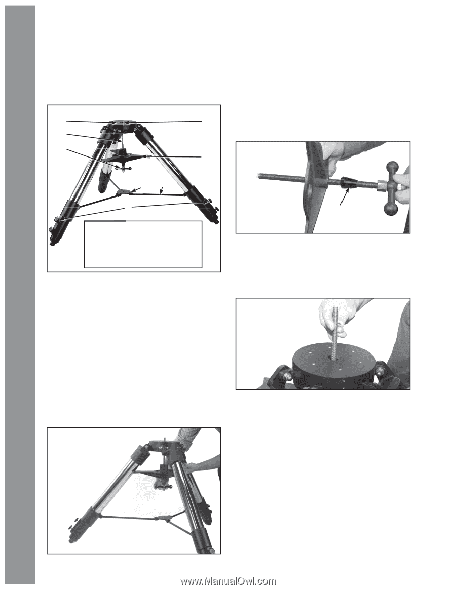
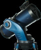
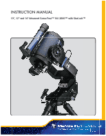
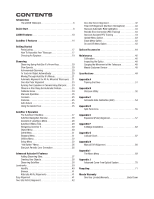
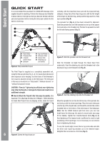
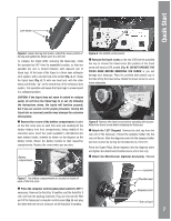
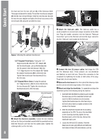
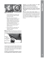
AutoStar #497QuHiAcNkDStBaOrtX QUICK START It is recommended that you attach the LX600 ACF telescope to the supplied tripod for observing. Perform the telescope and AutoStar II setup indoors in the light so that you become familiar with the parts and operation before moving the telescope outside into the dark for observing. B I C D E vertically, with the tripod feet down and with the tripod still fully collapsed. Grasp two of the tripod legs and, with the full weight of the tripod on the third leg, gently pull the legs apart to a fully open position (Fig. B). The spreader bar (Fig. A, 4) has been removed for shipment. Slide the spreader bar onto the threaded rod on top of the spacer that is already on the threaded rod. Position the spreader bar with the flat side facing upward (Fig. C). HG F Spacer B Tripod Head C Threaded Rod D T-handle Tension Knob E Spreader F Leg Lock Knobs G Extension Strut H Tension Hub I Retaining clip (not visible) Figure A. Fully assembled tripod. Figure C. Slide the spreader onto the threaded rod. Slide the threaded rod back through the tripod head from underneath. Push the retaining clip onto the threaded rod in the depressed ring on the threaded rod (Fig. D). The Field Tripod is supplied as a completely assembled unit, except for the spreader bar (Fig. A, 4). For visual observations and short exposure astro-imaging, the drive base of the telescope's fork mount is attached directly to the field tripod. The telescope in this way is mounted in an "Altazimuth" ("Altitude-Azimuth" or "vertical-horizontal") format. CAUTION: "Firm feel" tightening is sufficient; over-tightening may strip the threads or damage the tripod and results in no additional strength. B How to Attach the Tripod to the Telescope Assembly. (See Appendix F for attaching the tripod to X-Wedge. ) After removing the Giant Field Tripod from its shipping carton, stand the tripod Figure D. Push the retaining clip onto the threaded rod. Move the spreader bar so that the three arms of the spreader bar are lined up with the three tripod legs. Place the entire telescope onto the top of the tripod head, and thread the rod into the central threaded hole in the bottom of the drive base of the telescope. Note: that the LX600 features split fork arms; you can now break down the telescope into easier to mount parts (see page 55 for details). Tighten the T-handle tension knob (Fig. A, 3); firm tightening of the tension knob is sufficient to result in rigid positioning of the tripod legs. It is not necessary to use extreme force in tightening this knob. 6 Figure B. Extend the tripod legs out. To vary the tripod height, loosen the six leg lock knobs and slide the three inner tripod leg sections out to the desired height. Retighten the lock knobs to a firm feel (Fig. E).
-
 1
1 -
 2
2 -
 3
3 -
 4
4 -
 5
5 -
 6
6 -
 7
7 -
 8
8 -
 9
9 -
 10
10 -
 11
11 -
 12
12 -
13
-
14
-
15
-
16
-
17
-
18
-
19
-
20
-
21
-
22
-
23
-
24
-
25
-
26
-
27
-
28
-
29
-
30
-
31
-
32
-
33
-
34
-
35
-
36
-
37
-
38
-
39
-
40
-
41
-
42
-
43
-
44
-
45
-
46
-
47
-
48
-
49
-
50
-
51
-
52
-
53
-
54
-
55
-
56
-
57
-
58
-
59
-
60
-
61
-
62
-
63
-
64
-
65
-
66
-
67
-
68
-
69
-
70
-
71
-
72
 |
 |