Meade Tripod LX600-ACF 14 inch User Manual - Page 63
Appendix F
 |
View all Meade Tripod LX600-ACF 14 inch manuals
Add to My Manuals
Save this manual to your list of manuals |
Page 63 highlights
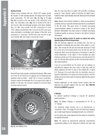
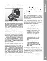
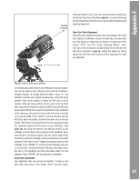
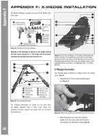
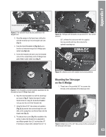
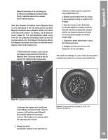
Appendix F Azimuth thrust bar pin Figure E. The azimuth thrust bar pin positioned in the tangent arm. 3. Place the wedge on the tripod head, sliding the azimuth thrust bar pin into the tangent arm slot (Fig. E). 4. Push the tripod threaded rod (Fig. B, 2) up so that the rod extends through the X-Wedge plate center hole (Fig C, 8). 5. Screw the threaded rod insert onto the threaded rod until it is seated firmly on the X-Wedge base plate, fitted in plate center hole (Fig. F). Figure G. X-Wedge with threaded rod cap and 5/16" hex screws secured. 65°, unthread the lock screw with the supplied hex key wrench and move the screw to the optional mounting hole. Latitude lock screw (in 25˚ to 57˚ position Latitude lock screw hole for 32˚ to 65˚ Figure F. The Threaded rod insert properly positioned on the threaded rod and X-Wedge base plate. 6. Align the tripod spreader bar with the tripod legs as shown in Fig, B. Tighten the tripod t-handle tension knob to a snug fit. Screw the threaded rod cap onto the end of the threaded rod. 7. Using the three 5/16" hex screws and washers (Fig. A, 5) pass the hex screws through the oval slots on the wedge floor and thread them into the tripod head (Fig. G). 8. The latitude lock screw (Fig. H) is installed at the factory to allow the tilt plate to be adjusted for any latitude greater than 25° and less than 57°. If viewing in a region with a latitude from 57° to Figure H. Latitude screw with multiple lock screw positions. Mounting the Telescope on the X-Wedge 1. Thread one of the provided 3/8" hex screws into the hole on the underside of the telescope drive Figure I. Attach one of the 3/8" hex screws to the curved part of the telescope drive base. 63
-
 1
1 -
2
-
3
-
4
-
5
-
6
-
7
-
8
-
9
-
10
-
11
-
12
-
13
-
14
-
15
-
16
-
17
-
18
-
19
-
20
-
21
-
22
-
23
-
24
-
25
-
26
-
27
-
28
-
29
-
30
-
31
-
32
-
33
-
34
-
35
-
36
-
37
-
38
-
39
-
40
-
41
-
42
-
43
-
44
-
45
-
46
-
47
-
48
-
49
-
50
-
51
-
52
-
53
-
54
-
55
-
56
-
57
-
 58
58 -
 59
59 -
 60
60 -
 61
61 -
 62
62 -
 63
63 -
 64
64 -
 65
65 -
 66
66 -
 67
67 -
 68
68 -
69
-
70
-
71
-
72
 |
 |
