Philips DVDR600VR User manual - Page 12
Connecting to a TV Only, TV has Component Video In Jacks - owners manual
 |
UPC - 037849948699
View all Philips DVDR600VR manuals
Add to My Manuals
Save this manual to your list of manuals |
Page 12 highlights
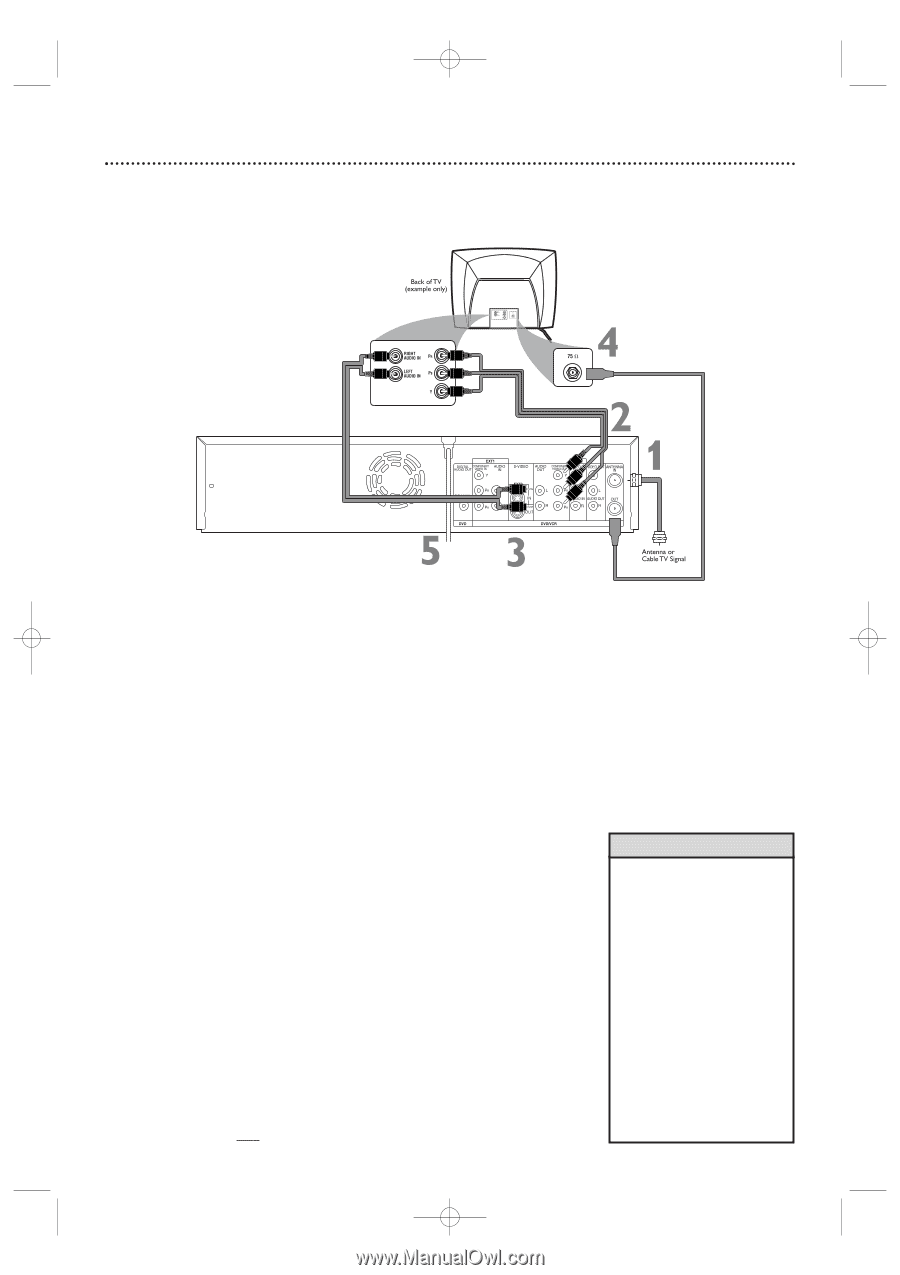
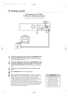
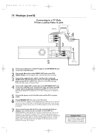
E9480UD_EN.qx3 05.1.8 4:15 PM Page 12 12 Hookups (cont'd) Connecting to a TV Only TV has Component Video In Jacks 1 Connect your Antenna or Cable TV signal to the ANTENNA IN jack on the rear of the Recorder. 2 Connect the Recorder's COMPONENT VIDEO OUT (Y PB PR) jacks to the TV's COMPONENT VIDEO IN jacks. Use component video cable (not supplied), which has red, blue, and green markings. Match the cable colors to the jack colors. 3 Connect the Recorder's white/red AUDIO OUT L/R (left/right) jacks to the TV's left/right AUDIO IN jacks. Use the supplied two-strand audio cable, which has red and white markings. Match cable colors to jack colors. 4 Connect the supplied RF coaxial cable to the Recorder's ANTENNA OUT jack and to the Antenna In jack on your TV. Your TV's Antenna In jack may be labelled RF In,Antenna In, or 75 ohm. Check your TV's manual for details. 5 Connect the power cords of the Recorder and the TV to a power outlet. 6 Press STANDBY-ON y to turn on the Recorder. If "IS TV ON? C03" appears on the display panel, you need to turn on your TV and set it to the correct Component Video In channel. (See next step.) You cannot see the Initial Setup screens until you turn on the TV and have it on the correct Component Video In channel. 7 Turn on the TV power. Set the TV to the Component Video In channel. It is not channel 3 or 4 when you use Component Video. See your TV owner's manual for details. Your TV remote may have a button or switch that selects the Component Video In channel. Or, go to your lowest TV channel and change channels down until you see the DVD background picture or Initial Setup screen on the TV. The Initial Setup screen will appear the first time you turn on the Recorder. Go to page 18 to continue. NOTE:When using the Component Video jacks, make sure Component video output is set to Interlaced. Set Component video output to Progressive Scan only if your TV has Progressive Scan. See page 63. Helpful Hints • If your TV has Progressive Scan, connect the Recorder's COMPONENT VIDEO OUT (Y PB PR) jacks to the TV's Progressive Scan In jacks instead. Progressive Scan produces a clearer picture by doubling the number of visible picture lines per field, providing a jitter-free, sharp, quiet picture. Check your TV manual for details. Set the Recorder's Video output to Progressive Scan. See page 63. • On the TV, the Component Video In jacks may be labeled YUV or Pr/Cr Pb/Cb Y and may be green, blue, and red.
-
 1
1 -
2
-
3
-
4
-
5
-
6
-
 7
7 -
 8
8 -
 9
9 -
 10
10 -
 11
11 -
 12
12 -
 13
13 -
 14
14 -
 15
15 -
 16
16 -
 17
17 -
18
-
19
-
20
-
21
-
22
-
23
-
24
-
25
-
26
-
27
-
28
-
29
-
30
-
31
-
32
-
33
-
34
-
35
-
36
-
37
-
38
-
39
-
40
-
41
-
42
-
43
-
44
-
45
-
46
-
47
-
48
-
49
-
50
-
51
-
52
-
53
-
54
-
55
-
56
-
57
-
58
-
59
-
60
-
61
-
62
-
63
-
64
-
65
-
66
-
67
-
68
-
69
-
70
-
71
-
72
-
73
-
74
-
75
-
76
-
77
-
78
-
79
-
80
-
81
-
82
-
83
-
84
-
85
-
86
-
87
-
88
 |
 |