Pioneer VSX-1021-K Owner's Manual - Page 11
Connecting your equipment - subwoofer
 |
UPC - 884938132978
View all Pioneer VSX-1021-K manuals
Add to My Manuals
Save this manual to your list of manuals |
Page 11 highlights
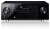
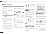
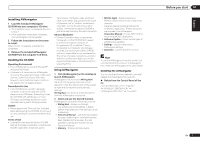
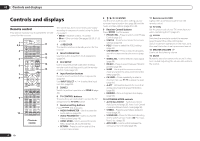
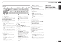
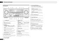
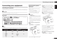
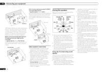
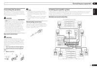
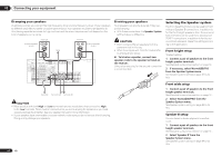
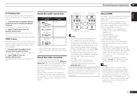
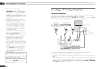
Connecting your equipment 03 Connecting your equipment Connecting your equipment This receiver provides you with many connection possibilities, but it doesn't have to be difficult. This chapter explains the kinds of components you can connect to make up your home theater system. CAUTION Before making or changing the connections, switch off the power and disconnect the power cord from the power outlet. Plugging in should be the final step. Rear panel HDMI IN 1 ASSIGNABLE 1 VIDEO 1 IN BD IN DVD IN DVR/BDR IN OUT DC OUTPUT for WIRELESS LAN LAN (10/100) COAXIAL ASSIGNABLE IN 1 IN 2 IN 1 IN 2 OPTICAL ASSIGNABLE CONTROL IN OUT IR IN VIDEO ZONE 2 AUDIO DVR/BDR CD-R/TAPE ZONE 2 (OUTPUT 5 V 0.6 A MAX) OUT MONITOR OUT TV/SAT VIDEO 1 IN IN OUT L ADAPTER PORT (OUTPUT 5 V OUT 0.1 A MAX) R ANTENNA (DVD) (CD) (TV/SAT) (DVR/BDR) OUT DVR/ BDR OUT IN 1 (DVD) ASSIGN ABLE IN 2 (DVR/ BDR) IN DVD IN IN IN CD FM UNBAL L 75 AM LOOP IN SIRIUS A R FRONT R L IN L IN CENTER SURROUND R L SURROUND BACK / ZONE 2 R L(Single) FRONT HEIGHT / WIDE / R L B MONITOR OUT Y PB PR COMPONENT VIDEO R TV/SAT VIDEO 1 DVD SUBWOOFER CAUTION: ATTENTION: PRE OUT SPEAKER IMPEDANCE ENCEINTE D'IMPEDANCE DE 6 -16 . 6 -16 . SPEAKERS SELECTABLE SEE INSTRUCTION MANUAL Class 2Wiring SELECTABLE VOIR LE MODE D'EMPLOI Note The input functions below are assigned by default to the receiver's different input terminals. Refer to The Input Setup menu on page 25 to change the assignments if other connections are used. Input function DVD BD TV/SAT DVR/BDR VIDEO 1 HDMI 1 CD Digital COAX-1 OPT-1 OPT-2 COAX-2 Input Terminals HDMI (DVD) (BD) Component IN 1 (DVR/BDR) IN 2 (VIDEO 1) IN 1 Determining the speakers' application This unit permits you to build various surround systems, in accordance with the number of speakers you have. ! Be sure to connect speakers to the front left and right channels (L and R). ! It is also possible to only connect one of the surround back speakers (SB) or neither. Choose one from Plans [A] to [E] below. Important ! The Speaker System setting must be made if you use any of the connections shown below other than [A] (see Speaker system setting on page 64 ). ! Sound does not come through simultaneously from the front height, front wide, speaker B and surround back speakers. Output speakers are different depending on the input signal or listening mode. [A] 7.1 channel surround system (Front height) *Default setting ! Speaker System setting: Normal(SB/FH) FHL FHR R L C SR SW SBR SL SBL A 7.1 ch surround system connects the left and right front speakers (L/R), the center speaker (C), the left and right front height speakers (FHL/FHR), the left and right surround speakers (SL/SR), the left and right surround back speakers (SBL/SBR), and the subwoofer (SW). It is not possible to produce sound simultaneously from the front height or front wide speakers and the surround back speakers. This surround system produces a more true-tolife sound from above. [B] 7.1 channel surround system (Front wide) ! Speaker System setting: Normal(SB/FW) L SW FWL SL R FWR C SR SBL SBR This plan replaces the left and right front height speakers shown in [A] with the left and right front wide speakers (FWL/FWR). It is not possible to produce sound simultaneously from the front height or front wide speakers and the surround back speakers. This surround system produces a true-to-life sound over a wider area. [C] 7.1 channel surround system & Speaker B connection ! Speaker System setting: Speaker B En 11
-
 1
1 -
2
-
3
-
4
-
5
-
 6
6 -
 7
7 -
 8
8 -
 9
9 -
 10
10 -
 11
11 -
 12
12 -
 13
13 -
 14
14 -
 15
15 -
 16
16 -
17
-
18
-
19
-
20
-
21
-
22
-
23
-
24
-
25
-
26
-
27
-
28
-
29
-
30
-
31
-
32
-
33
-
34
-
35
-
36
-
37
-
38
-
39
-
40
-
41
-
42
-
43
-
44
-
45
-
46
-
47
-
48
-
49
-
50
-
51
-
52
-
53
-
54
-
55
-
56
-
57
-
58
-
59
-
60
-
61
-
62
-
63
-
64
-
65
-
66
-
67
-
68
-
69
-
70
-
71
-
72
-
73
-
74
-
75
-
76
-
77
-
78
-
79
-
80
-
81
-
82
-
83
-
84
-
85
-
86
-
87
-
88
-
89
-
90
-
91
-
92
-
93
-
94
-
95
-
96
-
97
-
98
-
99
-
100
-
101
-
102
-
103
-
104
-
105
-
106
-
107
-
108
-
109
-
110
-
111
-
112
-
113
-
114
-
115
-
116
-
117
-
118
-
119
-
120
-
121
-
122
-
123
-
124
-
125
-
126
-
127
-
128
-
129
-
130
-
131
-
132
-
133
-
134
-
135
-
136
-
137
-
138
-
139
-
140
-
141
-
142
-
143
-
144
-
145
-
146
-
147
-
148
-
149
-
150
-
151
-
152
-
153
-
154
-
155
-
156
-
157
-
158
-
159
-
160
-
161
-
162
-
163
-
164
-
165
-
166
-
167
-
168
-
169
-
170
-
171
-
172
-
173
-
174
-
175
-
176
-
177
-
178
-
179
-
180
-
181
-
182
-
183
-
184
 |
 |
