Pioneer VSX-1021-K Owner's Manual - Page 18
Select one - zone 2 setup
 |
UPC - 884938132978
View all Pioneer VSX-1021-K manuals
Add to My Manuals
Save this manual to your list of manuals |
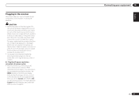
Page 18 highlights
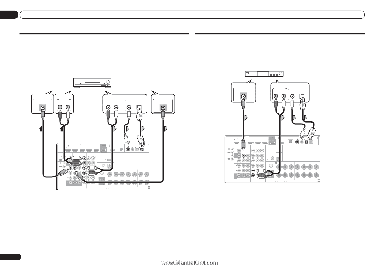
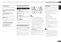
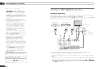
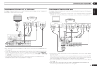
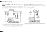
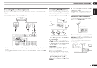
03 Connecting your equipment Connecting an HDD/DVD recorder, BD recorder and other video sources This receiver has two sets of audio/video inputs and outputs suitable for connecting analog or digital video devices, including HDD/DVD recorders and BD recorders. When you set up the receiver you'll need to tell the receiver which input you connected the recorder to (see also The Input Setup menu on page 25 ). HDD/DVD recorder, BD recorder, etc. Connecting a satellite/cable receiver or other set-top box Satellite and cable receivers, and terrestrial digital TV tuners are all examples of so-called 'set-top boxes'. When you set up the receiver you'll need to tell the receiver which input you connected the set-top box to (see The Input Setup menu on page 25 ). STB VIDEO IN VIDEO AUDIO IN R ANALOG L Select one AUDIO OUT DIGITAL OUT R ANALOG L COAXIAL OPTICAL VIDEO OUT VIDEO VIDEO OUT VIDEO Select one AUDIO OUT DIGITAL OUT R ANALOG L COAXIAL OPTICAL HDMI IN 1 ASSIGNABLE 1 VIDEO 1 IN BD IN DVD IN DVR/BDR IN OUT DC OUTPUT for WIRELESS LAN LAN (10/100) COAXIAL IN 1 ASSIGNABLE IN 2 IN 1 IN 2 OPTICAL ASSIGNABLE CONTROL IN OUT IR IN VIDEO ZONE 2 AUDIO DVR/BDR CD-R/TAPE ZONE 2 (OUTPUT 5 V 0.6 A MAX) OUT MONITOR OUT TV/SAT VIDEO 1 IN IN OUT L ADAPTER PORT (OUTPUT 5 V OUT 0.1 A MAX) R ANTENNA (DVD) (CD) (TV/SAT) (DVR/BDR) OUT DVR/ BDR OUT IN 1 (DVD) ASSIGN ABLE IN 2 (DVR/ BDR) IN DVD IN IN IN CD FM UNBAL L 75 AM LOOP IN SIRIUS A R FRONT R L IN L IN CENTER SURROUND R L SURROUND BACK / ZONE 2 R L(Single) MONITOR OUT Y PB PR COMPONENT VIDEO R TV/SAT VIDEO 1 DVD SUBWOOFER CAUTION: ATTENTION: PRE OUT SPEAKER IMPEDANCE ENCEINTE D'IMPEDANCE DE 6 -16 . 6 -16 . SPEAKERS SELEC Class 2Wiring SELEC ! In order to record, you must connect the analog audio cables (the digital connection is for playback only) (page 50). ! If your HDD/DVD recorder, BD recorder, etc., is equipped with an HDMI output terminal, we recommend connecting it to the receiver's HDMI DVR/BDR IN terminal. When doing so, also connect the receiver and TV by HDMI (see Connecting using HDMI on page 16 ). HDMI IN 1 VIDEO 1 IN ASSIGNABLE 1 BD IN DVD IN DVR/BDR IN OUT DC OUTPUT for WIRELESS LAN LAN (10/100) COAXIAL ASSIGNABLE IN 1 IN 2 IN 1 IN 2 OPTICAL ASSIGNABLE CONTROL IN OUT IR IN VIDEO ZONE 2 AUDIO DVR/BDR CD-R/TAPE ZONE 2 (OUTPUT 5 V 0.6 A MAX) OUT MONITOR OUT TV/SAT VIDEO 1 IN IN OUT L ADAPTER PORT (OUTPUT 5 V OUT 0.1 A MAX) R ANTENNA (DVD) (CD) (TV/SAT) (DVR/BDR) OUT DVR/ BDR OUT IN 1 (DVD) ASSIGN ABLE IN 2 (DVR/ BDR) IN DVD IN IN IN CD FM UNBAL L 75 AM LOOP IN SIRIUS A R FRONT R L IN L IN CENTER SURROUND R L SURROUND BACK / ZONE 2 F R L(Single) MONITOR OUT Y PB PR COMPONENT VIDEO R TV/SAT VIDEO 1 DVD SUBWOOFER CAUTION: ATTENTION: PRE OUT SPEAKER IMPEDANCE ENCEINTE D'IMPEDANCE DE 6 -16 . 6 -16 . SPEAKERS SELECT Class 2Wiring SELECT ! If your set-top box is equipped with an HDMI output terminal, we recommend connecting it to the receiver's HDMI IN 1 terminal. When doing so, also connect the receiver and TV by HDMI (see Connecting using HDMI on page 16 ). 18 En
-
 1
1 -
2
-
3
-
4
-
5
-
6
-
7
-
8
-
9
-
10
-
11
-
12
-
 13
13 -
 14
14 -
 15
15 -
 16
16 -
 17
17 -
 18
18 -
 19
19 -
 20
20 -
 21
21 -
 22
22 -
 23
23 -
24
-
25
-
26
-
27
-
28
-
29
-
30
-
31
-
32
-
33
-
34
-
35
-
36
-
37
-
38
-
39
-
40
-
41
-
42
-
43
-
44
-
45
-
46
-
47
-
48
-
49
-
50
-
51
-
52
-
53
-
54
-
55
-
56
-
57
-
58
-
59
-
60
-
61
-
62
-
63
-
64
-
65
-
66
-
67
-
68
-
69
-
70
-
71
-
72
-
73
-
74
-
75
-
76
-
77
-
78
-
79
-
80
-
81
-
82
-
83
-
84
-
85
-
86
-
87
-
88
-
89
-
90
-
91
-
92
-
93
-
94
-
95
-
96
-
97
-
98
-
99
-
100
-
101
-
102
-
103
-
104
-
105
-
106
-
107
-
108
-
109
-
110
-
111
-
112
-
113
-
114
-
115
-
116
-
117
-
118
-
119
-
120
-
121
-
122
-
123
-
124
-
125
-
126
-
127
-
128
-
129
-
130
-
131
-
132
-
133
-
134
-
135
-
136
-
137
-
138
-
139
-
140
-
141
-
142
-
143
-
144
-
145
-
146
-
147
-
148
-
149
-
150
-
151
-
152
-
153
-
154
-
155
-
156
-
157
-
158
-
159
-
160
-
161
-
162
-
163
-
164
-
165
-
166
-
167
-
168
-
169
-
170
-
171
-
172
-
173
-
174
-
175
-
176
-
177
-
178
-
179
-
180
-
181
-
182
-
183
-
184
 |
 |