Pioneer VSX-1021-K Owner's Manual - Page 19
the tabs to secure the AM antenna wires. - zone 2
 |
UPC - 884938132978
View all Pioneer VSX-1021-K manuals
Add to My Manuals
Save this manual to your list of manuals |
Page 19 highlights
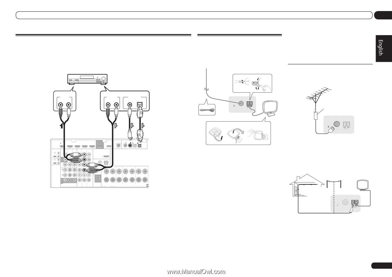
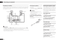
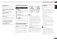
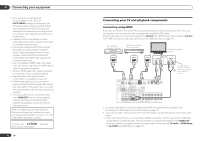
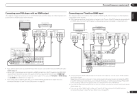
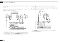
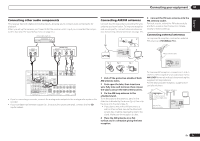
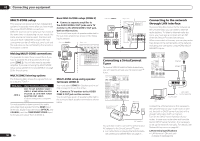
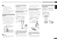
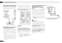
Connecting your equipment 03 Connecting other audio components This receiver has both digital and analog inputs, allowing you to connect audio components for playback. When you set up the receiver you'll need to tell the receiver which input you connected the component to (see also The Input Setup menu on page 25 ). CD-R, MD, DAT, etc. Connecting AM/FM antennas Connect the AM loop antenna and the FM wire antenna as shown below. To improve reception and sound quality, connect external antennas (see Connecting external antennas on page 19 ). 1 2 5 Connect the FM wire antenna into the FM antenna socket. For best results, extend the FM antenna fully and fix to a wall or door frame. Don't drape loosely or leave coiled up. Connecting external antennas To improve FM reception, connect an external FM antenna to FM UNBAL 75 W. AUDIO IN R ANALOG L Select one AUDIO OUT DIGITAL OUT R ANALOG L COAXIAL OPTICAL 5 fig. a ANTENNA FM UNBAL 75 AM LOOP 3 4 fig. b fig. c 75 Ω coaxial cable ANTENNA FM UNBAL 75 AM LOOP HDMI IN 1 ASSIGNABLE 1 VIDEO 1 IN BD IN DVD IN DVR/BDR IN OUT DC OUTPUT for WIRELESS LAN LAN (10/100) COAXIAL IN 1 ASSIGNABLE IN 2 IN 1 IN 2 OPTICAL ASSIGNABLE CONTROL IN OUT IR IN VIDEO ZONE 2 AUDIO DVR/BDR CD-R/TAPE ZONE 2 (OUTPUT 5 V 0.6 A MAX) OUT MONITOR OUT TV/SAT VIDEO 1 IN IN OUT L ADAPTER PORT (OUTPUT 5 V OUT 0.1 A MAX) R ANTENNA (DVD) (CD) (TV/SAT) (DVR/BDR) OUT DVR/ BDR OUT IN 1 (DVD) ASSIGN ABLE IN 2 (DVR/ BDR) IN DVD IN IN IN CD FM UNBAL L 75 AM LOOP IN SIRIUS A R FRONT R L IN L IN CENTER SURROUND R L SURROUND BACK / ZONE 2 R L(Single) MONITOR OUT Y PB PR COMPONENT VIDEO R TV/SAT VIDEO 1 DVD SUBWOOFER CAUTION: ATTENTION: PRE OUT SPEAKER IMPEDANCE ENCEINTE D'IMPEDANCE DE 6 -16 . 6 -16 . SPEAKERS SELEC Class 2Wiring SELEC ! If you're connecting a recorder, connect the analog audio outputs to the analog audio inputs on the recorder. ! If your turntable has line-level outputs (i.e., it has a built-in phono pre-amp), connect it to the CD inputs instead. 1 Pull off the protective shields of both AM antenna wires. 2 Push open the tabs, then insert one wire fully into each terminal, then release the tabs to secure the AM antenna wires. 3 Fix the AM loop antenna to the attached stand. To fix the stand to the antenna, bend in the direction indicated by the arrow (fig. a) then clip the loop onto the stand (fig. b). ! If you plan to mount the AM antenna to a wall or other surface, secure the stand with screws (fig. c) before clipping the loop to the stand. Make sure the reception is clear. 4 Place the AM antenna on a flat surface and in a direction giving the best reception. To improve AM reception, connect a 5 m to 6 m (16 ft. to 20 ft.) length of vinyl-coated wire to the AM LOOP terminals without disconnecting the supplied AM loop antenna. For the best possible reception, suspend horizontally outdoors. Outdoor antenna Indoor antenna (vinyl-coated wire) 5 m to 6 m (16 ft. to 20 ft.) ANTENNA FM UNBAL 75 AM LOOP En 19
-
 1
1 -
2
-
3
-
4
-
5
-
6
-
7
-
8
-
9
-
10
-
11
-
12
-
13
-
 14
14 -
 15
15 -
 16
16 -
 17
17 -
 18
18 -
 19
19 -
 20
20 -
 21
21 -
 22
22 -
 23
23 -
 24
24 -
25
-
26
-
27
-
28
-
29
-
30
-
31
-
32
-
33
-
34
-
35
-
36
-
37
-
38
-
39
-
40
-
41
-
42
-
43
-
44
-
45
-
46
-
47
-
48
-
49
-
50
-
51
-
52
-
53
-
54
-
55
-
56
-
57
-
58
-
59
-
60
-
61
-
62
-
63
-
64
-
65
-
66
-
67
-
68
-
69
-
70
-
71
-
72
-
73
-
74
-
75
-
76
-
77
-
78
-
79
-
80
-
81
-
82
-
83
-
84
-
85
-
86
-
87
-
88
-
89
-
90
-
91
-
92
-
93
-
94
-
95
-
96
-
97
-
98
-
99
-
100
-
101
-
102
-
103
-
104
-
105
-
106
-
107
-
108
-
109
-
110
-
111
-
112
-
113
-
114
-
115
-
116
-
117
-
118
-
119
-
120
-
121
-
122
-
123
-
124
-
125
-
126
-
127
-
128
-
129
-
130
-
131
-
132
-
133
-
134
-
135
-
136
-
137
-
138
-
139
-
140
-
141
-
142
-
143
-
144
-
145
-
146
-
147
-
148
-
149
-
150
-
151
-
152
-
153
-
154
-
155
-
156
-
157
-
158
-
159
-
160
-
161
-
162
-
163
-
164
-
165
-
166
-
167
-
168
-
169
-
170
-
171
-
172
-
173
-
174
-
175
-
176
-
177
-
178
-
179
-
180
-
181
-
182
-
183
-
184
 |
 |