Pioneer VSX-1021-K Owner's Manual - Page 13
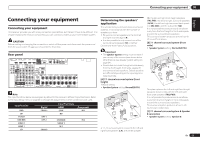
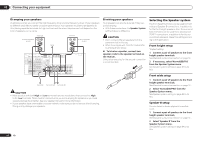
Twist exposed wire strands together., Loosen terminal and insert exposed, wire., Tighten terminal. - manual
 |
UPC - 884938132978
View all Pioneer VSX-1021-K manuals
Add to My Manuals
Save this manual to your list of manuals |
Page 13 highlights
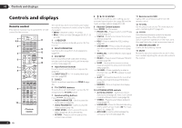
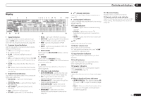
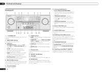
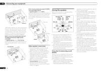
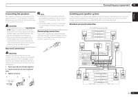
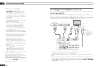
Connecting your equipment 03 Connecting the speakers Each speaker connection on the receiver comprises a positive (+) and negative (-) terminal. Make sure to match these up with the terminals on the speakers themselves. CAUTION ! These speaker terminals carry HAZARDOUS LIVE voltage. To prevent the risk of electric shock when connecting or disconnecting the speaker cables, disconnect the power cord before touching any uninsulated parts. ! Make sure that all the bare speaker wire is twisted together and inserted fully into the speaker terminal. If any of the bare speaker wire touches the back panel it may cause the power to cut off as a safety measure. Note ! Please refer to the manual that came with your speakers for details on how to connect the other end of the speaker cables to your speakers. ! Use an RCA cable to connect the subwoofer. It is not possible to connect using speaker cables. Banana plug connections If you want to use speaker cables terminated with banana plugs, screw the speaker terminal fully shut, then plug the banana plug into the end of the speaker terminal. Bare wire connections Installing your speaker system At the very least, front left and right speakers only are necessary. Note that your main surround speakers should always be connected as a pair, but you can connect just one surround back speaker if you like (it must be connected to the left surround back terminal). Standard surround connection The front height terminals can also be used for the front wide and Speaker B speakers. Front height setting Front height right Front height left Front wide setting Front wide right Front wide left Speaker B setting Speaker B - right Speaker B - left Front right Center Subwoofer LINE LEVEL INPUT Front left CAUTION Make sure that all speakers are securely installed. This not only improves sound quality, but also reduces the risk of damage or injury resulting from speakers being knocked over or falling in the event of external shocks such as earthquakes. 1 Twist exposed wire strands together. 2 Loosen terminal and insert exposed wire. 3 Tighten terminal. 1 2 3 10 mm (3/8 in.) HDMI IN 1 ASSIGNABLE 1 VIDEO 1 IN BD IN DVD IN DVR/BDR IN OUT DC OUTPUT for WIRELESS LAN LAN (10/100) COAXIAL IN 1 ASSIGNABLE IN 2 IN 1 IN 2 OPTICAL ASSIGNABLE CONTROL IN OUT IR IN VIDEO ZONE 2 AUDIO DVR/BDR CD-R/TAPE ZONE 2 (OUTPUT 5 V 0.6 A MAX) OUT MONITOR OUT TV/SAT VIDEO 1 IN IN OUT L ADAPTER PORT (OUTPUT 5 V OUT 0.1 A MAX) R ANTENNA (DVD) (CD) (TV/SAT) (DVR/BDR) OUT DVR/ BDR OUT IN 1 (DVD) ASSIGN ABLE IN 2 (DVR/ BDR) IN DVD IN IN IN CD FM UNBAL L 75 AM LOOP IN SIRIUS A R FRONT R L IN L IN CENTER SURROUND R L SURROUND BACK / ZONE 2 R L(Single) FRONT HEIGHT / WIDE / R L B MONITOR OUT Y PB PR COMPONENT VIDEO R TV/SAT VIDEO 1 DVD SUBWOOFER CAUTION: ATTENTION: PRE OUT SPEAKER IMPEDANCE ENCEINTE D'IMPEDANCE DE 6 -16 . 6 -16 . SPEAKERS SELECTABLE SEE INSTRUCTION MANUAL Class 2Wiring SELECTABLE VOIR LE MODE D'EMPLOI Surround right The surround back terminals can also be used for ZONE 2. 5.1 ch surround setting Not connected Not connected 6.1 ch surround setting Not connected Surround back 7.1 ch surround setting Surround back right Surround back left ZONE 2 - Right ZONE 2 setting ZONE 2 - Left Surround left En 13
-
 1
1 -
2
-
3
-
4
-
5
-
6
-
7
-
 8
8 -
 9
9 -
 10
10 -
 11
11 -
 12
12 -
 13
13 -
 14
14 -
 15
15 -
 16
16 -
 17
17 -
 18
18 -
19
-
20
-
21
-
22
-
23
-
24
-
25
-
26
-
27
-
28
-
29
-
30
-
31
-
32
-
33
-
34
-
35
-
36
-
37
-
38
-
39
-
40
-
41
-
42
-
43
-
44
-
45
-
46
-
47
-
48
-
49
-
50
-
51
-
52
-
53
-
54
-
55
-
56
-
57
-
58
-
59
-
60
-
61
-
62
-
63
-
64
-
65
-
66
-
67
-
68
-
69
-
70
-
71
-
72
-
73
-
74
-
75
-
76
-
77
-
78
-
79
-
80
-
81
-
82
-
83
-
84
-
85
-
86
-
87
-
88
-
89
-
90
-
91
-
92
-
93
-
94
-
95
-
96
-
97
-
98
-
99
-
100
-
101
-
102
-
103
-
104
-
105
-
106
-
107
-
108
-
109
-
110
-
111
-
112
-
113
-
114
-
115
-
116
-
117
-
118
-
119
-
120
-
121
-
122
-
123
-
124
-
125
-
126
-
127
-
128
-
129
-
130
-
131
-
132
-
133
-
134
-
135
-
136
-
137
-
138
-
139
-
140
-
141
-
142
-
143
-
144
-
145
-
146
-
147
-
148
-
149
-
150
-
151
-
152
-
153
-
154
-
155
-
156
-
157
-
158
-
159
-
160
-
161
-
162
-
163
-
164
-
165
-
166
-
167
-
168
-
169
-
170
-
171
-
172
-
173
-
174
-
175
-
176
-
177
-
178
-
179
-
180
-
181
-
182
-
183
-
184
 |
 |
