Pioneer VSX-1021-K Owner's Manual - Page 20
both on this receiver. - internet radio
 |
UPC - 884938132978
View all Pioneer VSX-1021-K manuals
Add to My Manuals
Save this manual to your list of manuals |
Page 20 highlights
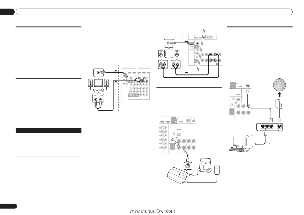
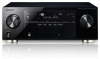
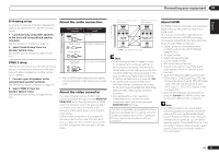
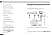
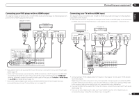
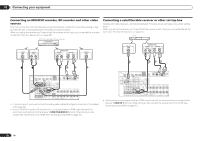
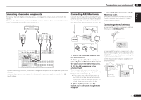
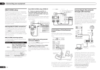
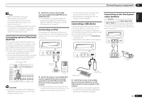
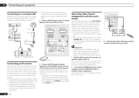
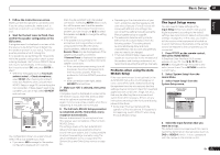
03 Connecting your equipment MULTI-ZONE setup This receiver can power up to two independent systems in separate rooms after you have made the proper MULTI-ZONE connections. Different sources can be playing in two zones at the same time or, depending on your needs, the same source can also be used. The main and sub zone have independent power (the main zone power can be off while sub zone is on) and the sub zone can be controlled by the remote or front panel controls. Making MULTI-ZONE connections It is possible to make these connections if you have a separate TV and speakers for the sub zone (ZONE 2). You will also need a separate amplifier if you are not using the MULTI-ZONE setup using speaker terminals (ZONE 2) on page 20 for the sub zone. MULTI-ZONE listening options The following table shows the signals that can be output to ZONE 2: Sub Zone Input functions available ZONE 2 DVD, TV/SAT, DVR/BDR, VIDEO 1, VIDEO 2, HOME MEDIA GALLERY, iPod/USB, CD, CD-R/TAPE, TUNER, ADAPTER PORT, SIRIUS (Outputs analog audio, composite video.) It is not possible to down-convert the audio and video input signals from the HDMI input terminals, digital input terminals (OPTICAL and COAXIAL) and the COMPONENT VIDEO input terminals and output them to ZONE 2. 20 En Basic MULTI-ZONE setup (ZONE 2) % Connect a separate amplifier to the AUDIO ZONE 2 OUT jacks and a TV monitor to the VIDEO ZONE 2 OUT jack, both on this receiver. You should have a pair of speakers attached to the sub zone amplifier as shown in the following illustration. Sub zone (ZONE 2) VIDEO IN AUDIO IN R L Main zone HDMI IN 1 ASSIGNABLE 1 VIDEO 1 IN BD IN DVD IN DVR/BDR IN CONTROL IN OUT IR IN VIDEO ZONE 2 AUDIO DVR/BDR CD-R/TAPE ZONE 2 OUT MONITOR OUT TV/SAT VIDEO 1 IN IN OUT L OUT R AN OUT DVR/ BDR OUT IN 1 (DVD) ASSIGN ABLE IN 2 (DVR/ BDR) IN DVD IN IN IN CD FM L 75 IN SIR R L IN MONITOR OUT Y PB PR COMPONENT VIDEO R TV/SAT VIDEO 1 DVD MULTI-ZONE setup using speaker terminals (ZONE 2) You must select ZONE 2 in Speaker system setting on page 64 to use this setup. % Connect a TV monitor to the VIDEO ZONE 2 OUT jack on this receiver. You should have a pair of speakers attached to the surround back speaker terminals as shown below. Sub zone (ZONE 2) VIDEO IN L R Main zone HDMI IN 1 ASSIGNABLE 1 VIDECOO1AINXIAL IN 1 ASSIGNABLE IN 2 IN 1 IN 2 OPTICAL ASSIGNABLE CONTROL IN OUT IR IN VIDEO ZONE 2 (DVD) OUT MONITOR OUT TV/SAT IN (CD) (TV/SAT) (DVR/BDR) OUT DVR/ BDR OUT IN 1 (DVD) ASSIGN ABLE IN 2 (DVR/ BDR) IN SURROUND R L SURROUND BACK / ZONE 2 FRONT HEIG R L(Single) R MONITOR OUT Y PB COMPONENT VI SPEAKERS SELECTABLE SEE INST Class 2Wiring SELECTABLE VOIR LE M Connecting to the network through LAN interface By connecting this receiver to the network via the LAN terminal, you can listen to Internet radio stations. To listen to Internet radio stations, you must sign a contract with an ISP (Internet Service Provider) beforehand. When connected in this way, you can play audio files stored on the components on the network, including your computer, using HOME MEDIA GALLERY inputs. Connecting a SiriusConnect Tuner To receive SIRIUS Satellite Radio broadcasts, you will need to activate your SiriusConnectTM tuner. DVD IN DVR/BDR IN OUT DC OUTPUT for WIRELESS LAN LAN(10/100) COAXIAL AS IN 1 O R CD-R/TAPE ZONE 2 (OUTPUT 5 V 0.6 A MAX) L ADAPTER PORT (OUTPUT 5 V OUT 0.1 A MAX) R ANTENNA CD FM UNBAL L 75 AM LOOP IN SIRIUS A R FRONT R L CENTER IN L IN R T VIDEO 1 DVD SUBWOOFER CAUTION: ATTENTION: PRE OUT SPEAKER IMPEDANCE ENCEINTE D'IMPEDANCE DE 6 -16 . 6 -16 . (DVD) SUR R SiriusConnectTM HOME tuner SIRIUS H Antenna SIRIUS H AC adapter You will also need to connect the antenna and AC adapter to the SiriusConnectTM tuner. ! For instructions on playing the SIRIUS Radio, see Listening to Satellite Radio on page 31 . OUT DC OUTPUT for WIRELESS LAN LAN(10/100) C (OUTPUT 5 V 0.6 A MAX) ADAPTER PORT (OUTPUT 5 V 0.1 A MAX) TENNA UNBAL AM LOOP RIUS A FRONT R L CENTER IN SUBWOOFER CAUTION: ATTENTION: PRE OUT SPEAKER IMPEDANCE ENCEINTE D'IMPEDANCE DE 6 -16 . 6 -16 . Internet Modem LAN 3 2 1 WAN Router to LAN port LAN cable (sold separately) PC Connect the LAN terminal on this receiver to the LAN terminal on your router (with or without the built-in DHCP server function) with a straight LAN cable (CAT 5 or higher). Turn on the DHCP server function of your router. In case your router does not have the built-in DHCP server function, it is necessary to set up the network manually. For details, see Network Setup menu on page 66 . LAN terminal specifications ! LAN terminal : Ethernet jack (10BASE-T/100BASE-TX)
-
 1
1 -
2
-
3
-
4
-
5
-
6
-
7
-
8
-
9
-
10
-
11
-
12
-
13
-
14
-
 15
15 -
 16
16 -
 17
17 -
 18
18 -
 19
19 -
 20
20 -
 21
21 -
 22
22 -
 23
23 -
 24
24 -
 25
25 -
26
-
27
-
28
-
29
-
30
-
31
-
32
-
33
-
34
-
35
-
36
-
37
-
38
-
39
-
40
-
41
-
42
-
43
-
44
-
45
-
46
-
47
-
48
-
49
-
50
-
51
-
52
-
53
-
54
-
55
-
56
-
57
-
58
-
59
-
60
-
61
-
62
-
63
-
64
-
65
-
66
-
67
-
68
-
69
-
70
-
71
-
72
-
73
-
74
-
75
-
76
-
77
-
78
-
79
-
80
-
81
-
82
-
83
-
84
-
85
-
86
-
87
-
88
-
89
-
90
-
91
-
92
-
93
-
94
-
95
-
96
-
97
-
98
-
99
-
100
-
101
-
102
-
103
-
104
-
105
-
106
-
107
-
108
-
109
-
110
-
111
-
112
-
113
-
114
-
115
-
116
-
117
-
118
-
119
-
120
-
121
-
122
-
123
-
124
-
125
-
126
-
127
-
128
-
129
-
130
-
131
-
132
-
133
-
134
-
135
-
136
-
137
-
138
-
139
-
140
-
141
-
142
-
143
-
144
-
145
-
146
-
147
-
148
-
149
-
150
-
151
-
152
-
153
-
154
-
155
-
156
-
157
-
158
-
159
-
160
-
161
-
162
-
163
-
164
-
165
-
166
-
167
-
168
-
169
-
170
-
171
-
172
-
173
-
174
-
175
-
176
-
177
-
178
-
179
-
180
-
181
-
182
-
183
-
184
 |
 |