Sony RDR VX500 Operating Instructions - Page 23
Step 4: Connecting to Your AV/Amplifier Receiver, Hookups and Settings - instructions
 |
UPC - 027242657441
View all Sony RDR VX500 manuals
Add to My Manuals
Save this manual to your list of manuals |
Page 23 highlights
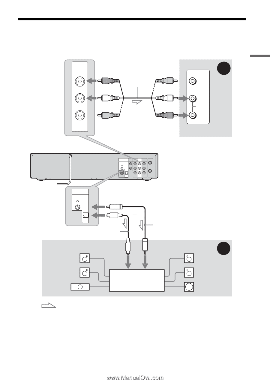
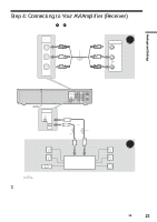
Hookups and Settings Step 4: Connecting to Your AV/Amplifier (Receiver) Select one of the following patterns A or B, according to the input jack on your AV amplifier (receiver). This will enable you to listen to DVD audio tracks through your AV amplifier (receiver). LINE OUT AUDIO VIDEO (red) (white) (yellow) Audio/video cord (supplied) (white) (yellow)* (red) to LINE OUT (AUDIO L/R) A INPUT VIDEO L AUDIO R AV amplifier (receiver) VCR-DVD recorder DIGITAL AUDIO OUT PCM/DTS/ DOLBY DIGITAL COAXIAL AUDIO OUT COMPONENT VIDEO OUT LINE OUT LINE 1 IN R Y R L PB AUDIO AUDIO L OPTICAL PR VHF/UHF IN OUT S VIDEO OUT VIDEO VIDEO DIGITAL AUDIO OUT PCM/DTS/ DOLBY DIGITAL COAXIAL OPTICAL to DIGITAL AUDIO OUT (COAXIAL or OPTICAL) or Optical digital cord (not supplied) Coaxial digital cord (not supplied) [Speakers] Rear (L) Front (L) Center to optical digital input to coaxial digital input AV amplifier (receiver) with a decoder B [Speakers] Rear (R) Front (R) Subwoofer : Signal flow * The yellow plug is used for video signals (page 18). z Hints • For correct speaker location, see the operating instructions supplied with the connected components. • Digital audio signal can also be output when playing a VHS tape. ,continued 23
-
 1
1 -
2
-
3
-
4
-
5
-
6
-
7
-
8
-
9
-
10
-
11
-
12
-
13
-
14
-
15
-
16
-
17
-
 18
18 -
 19
19 -
 20
20 -
 21
21 -
 22
22 -
 23
23 -
 24
24 -
 25
25 -
 26
26 -
 27
27 -
 28
28 -
29
-
30
-
31
-
32
-
33
-
34
-
35
-
36
-
37
-
38
-
39
-
40
-
41
-
42
-
43
-
44
-
45
-
46
-
47
-
48
-
49
-
50
-
51
-
52
-
53
-
54
-
55
-
56
-
57
-
58
-
59
-
60
-
61
-
62
-
63
-
64
-
65
-
66
-
67
-
68
-
69
-
70
-
71
-
72
-
73
-
74
-
75
-
76
-
77
-
78
-
79
-
80
-
81
-
82
-
83
-
84
-
85
-
86
-
87
-
88
-
89
-
90
-
91
-
92
-
93
-
94
-
95
-
96
-
97
-
98
-
99
-
100
-
101
-
102
-
103
-
104
-
105
-
106
-
107
-
108
-
109
-
110
-
111
-
112
-
113
-
114
-
115
-
116
-
117
-
118
-
119
-
120
-
121
-
122
-
123
-
124
-
125
-
126
-
127
-
128
 |
 |