TP-Link TL-SL5428E User Guide - Page 102
Port Config
 |
UPC - 845973020873
View all TP-Link TL-SL5428E manuals
Add to My Manuals
Save this manual to your list of manuals |
Page 102 highlights
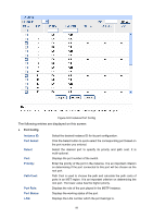
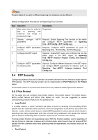
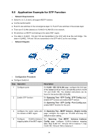
9.5 Application Example for STP Function ¾ Network Requirements z Switch A, B, C, D and E all support MSTP function. z A is the central switch. z B and C are switches in the convergence layer. D, E and F are switches in the access layer. z There are 6 VLANs labeled as VLAN101-VLAN106 in the network. z All switches run MSTP and belong to the same MST region. z The data in VLAN01, 103 and 105 are transmitted in the STP with B as the root bridge. The data in VLAN02, 104 and 106 are transmitted in the STP with C as the root bridge. ¾ Network Diagram ¾ Configuration Procedure z Configure Switch A: Step Operation 1 Configure ports 2 Enable STP function Description On VLAN→802.1Q VLAN page, configure the link type of the related ports as Trunk, and add the ports to VLAN 101 and VLAN 106. The detailed instructions can be found in the section 802.1Q VLAN. On Spanning Tree→STP Config→STP Config page, enable STP function and select MSTP version. On Spanning Tree→STP Config→Port Config page, enable MSTP function for the port. 3 Configure the region name and On Spanning Tree→MSTP Instance→Region Config the revision of MST region page, configure the region as TP-LINK and keep the default revision setting. 4 Configure VLAN-to-Instance On Spanning Tree→MSTP Instance→Instance mapping table of the MST region Config page, configure VLAN-to-Instance mapping table. Map VLAN 101, 103 and 105 to Instance 1; map VLAN 102, 104 and 106 to Instance 2. 94
-
 1
1 -
2
-
3
-
4
-
5
-
6
-
7
-
8
-
9
-
10
-
11
-
12
-
13
-
14
-
15
-
16
-
17
-
18
-
19
-
20
-
21
-
22
-
23
-
24
-
25
-
26
-
27
-
28
-
29
-
30
-
31
-
32
-
33
-
34
-
35
-
36
-
37
-
38
-
39
-
40
-
41
-
42
-
43
-
44
-
45
-
46
-
47
-
48
-
49
-
50
-
51
-
52
-
53
-
54
-
55
-
56
-
57
-
58
-
59
-
60
-
61
-
62
-
63
-
64
-
65
-
66
-
67
-
68
-
69
-
70
-
71
-
72
-
73
-
74
-
75
-
76
-
77
-
78
-
79
-
80
-
81
-
82
-
83
-
84
-
85
-
86
-
87
-
88
-
89
-
90
-
91
-
92
-
93
-
94
-
95
-
96
-
 97
97 -
 98
98 -
 99
99 -
 100
100 -
 101
101 -
 102
102 -
 103
103 -
 104
104 -
 105
105 -
 106
106 -
 107
107 -
108
-
109
-
110
-
111
-
112
-
113
-
114
-
115
-
116
-
117
-
118
-
119
-
120
-
121
-
122
-
123
-
124
-
125
-
126
-
127
-
128
-
129
-
130
-
131
-
132
-
133
-
134
-
135
-
136
-
137
-
138
-
139
-
140
-
141
-
142
-
143
-
144
-
145
-
146
-
147
-
148
-
149
-
150
-
151
-
152
-
153
-
154
-
155
-
156
-
157
-
158
-
159
-
160
-
161
-
162
-
163
-
164
-
165
-
166
-
167
-
168
-
169
-
170
-
171
-
172
-
173
-
174
-
175
-
176
-
177
-
178
-
179
-
180
-
181
-
182
-
183
-
184
-
185
-
186
-
187
-
188
-
189
-
190
-
191
-
192
-
193
-
194
-
195
-
196
-
197
-
198
-
199
-
200
-
201
-
202
-
203
-
204
-
205
-
206
-
207
-
208
-
209
-
210
-
211
-
212
-
213
-
214
-
215
-
216
-
217
-
218
-
219
-
220
-
221
-
222
-
223
-
224
-
225
-
226
-
227
-
228
-
229
-
230
-
231
-
232
-
233
-
234
-
235
-
236
-
237
-
238
-
239
-
240
-
241
-
242
-
243
-
244
-
245
-
246
-
247
-
248
-
249
-
250
 |
 |