TP-Link TL-SL5428E User Guide - Page 79
Port Enable
 |
UPC - 845973020873
View all TP-Link TL-SL5428E manuals
Add to My Manuals
Save this manual to your list of manuals |
Page 79 highlights
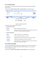
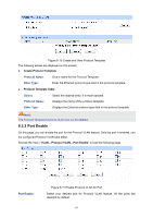
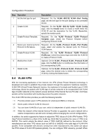
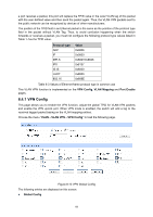
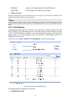
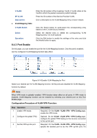
C VLAN: SP VLAN: Description: ¾ VLAN Mapping Table Enter the ID number of the Customer VLAN. C VLAN refers to the VLAN to which the packet received by switch belongs. Enter the ID number of the Service Provider VLAN. Give a description to the VLAN Mapping entry or leave it blank. C VLAN Select: Select: Operation: Click the Select button to quick-select the corresponding entry based on the C VLAN ID you entered. Select the desired entry to delete the corresponding VLAN Mapping entry. It is multi-optional. Click the Edit button to modify the settings of the entry and click the Modify button to apply. 8.4.3 Port Enable On this page, you can enable the port for the VLAN Mapping function. Only the port is enabled, can the configured VLAN Mapping function take effect. Figure 8-14 Enable VLAN Mapping for Port Select your desired port for VLAN Mapping function. All the ports are disabled for VLAN Mapping function by default. Note: When VPN mode is globally enabled, VPN function takes effect on all ports. If VPN mode is disabled, VLAN Mapping function can be enabled by selecting your desired port on this Port Enable page. Configuration Procedure of VLAN VPN Function: Step Operation 1 Enable VPN mode. 2 Configure the global TPID. 3 Set the VPN up-link port. Description Required. On the VLAN→VLAN VPN→VPN Config page, enable the VPN mode. Optional. On the VLAN→VLAN VPN→VPN Config page, configure the global TPID basing on the devices connected to the up-link port. Required. On the VLAN→VLAN VPN→VPN Config page, specify the desired port to be the VPN up-link port. It's 71
-
 1
1 -
2
-
3
-
4
-
5
-
6
-
7
-
8
-
9
-
10
-
11
-
12
-
13
-
14
-
15
-
16
-
17
-
18
-
19
-
20
-
21
-
22
-
23
-
24
-
25
-
26
-
27
-
28
-
29
-
30
-
31
-
32
-
33
-
34
-
35
-
36
-
37
-
38
-
39
-
40
-
41
-
42
-
43
-
44
-
45
-
46
-
47
-
48
-
49
-
50
-
51
-
52
-
53
-
54
-
55
-
56
-
57
-
58
-
59
-
60
-
61
-
62
-
63
-
64
-
65
-
66
-
67
-
68
-
69
-
70
-
71
-
72
-
73
-
 74
74 -
 75
75 -
 76
76 -
 77
77 -
 78
78 -
 79
79 -
 80
80 -
 81
81 -
 82
82 -
 83
83 -
 84
84 -
85
-
86
-
87
-
88
-
89
-
90
-
91
-
92
-
93
-
94
-
95
-
96
-
97
-
98
-
99
-
100
-
101
-
102
-
103
-
104
-
105
-
106
-
107
-
108
-
109
-
110
-
111
-
112
-
113
-
114
-
115
-
116
-
117
-
118
-
119
-
120
-
121
-
122
-
123
-
124
-
125
-
126
-
127
-
128
-
129
-
130
-
131
-
132
-
133
-
134
-
135
-
136
-
137
-
138
-
139
-
140
-
141
-
142
-
143
-
144
-
145
-
146
-
147
-
148
-
149
-
150
-
151
-
152
-
153
-
154
-
155
-
156
-
157
-
158
-
159
-
160
-
161
-
162
-
163
-
164
-
165
-
166
-
167
-
168
-
169
-
170
-
171
-
172
-
173
-
174
-
175
-
176
-
177
-
178
-
179
-
180
-
181
-
182
-
183
-
184
-
185
-
186
-
187
-
188
-
189
-
190
-
191
-
192
-
193
-
194
-
195
-
196
-
197
-
198
-
199
-
200
-
201
-
202
-
203
-
204
-
205
-
206
-
207
-
208
-
209
-
210
-
211
-
212
-
213
-
214
-
215
-
216
-
217
-
218
-
219
-
220
-
221
-
222
-
223
-
224
-
225
-
226
-
227
-
228
-
229
-
230
-
231
-
232
-
233
-
234
-
235
-
236
-
237
-
238
-
239
-
240
-
241
-
242
-
243
-
244
-
245
-
246
-
247
-
248
-
249
-
250
 |
 |