TP-Link TL-SL5428E User Guide - Page 15
Appearance Description - v3
 |
UPC - 845973020873
View all TP-Link TL-SL5428E manuals
Add to My Manuals
Save this manual to your list of manuals |
Page 15 highlights
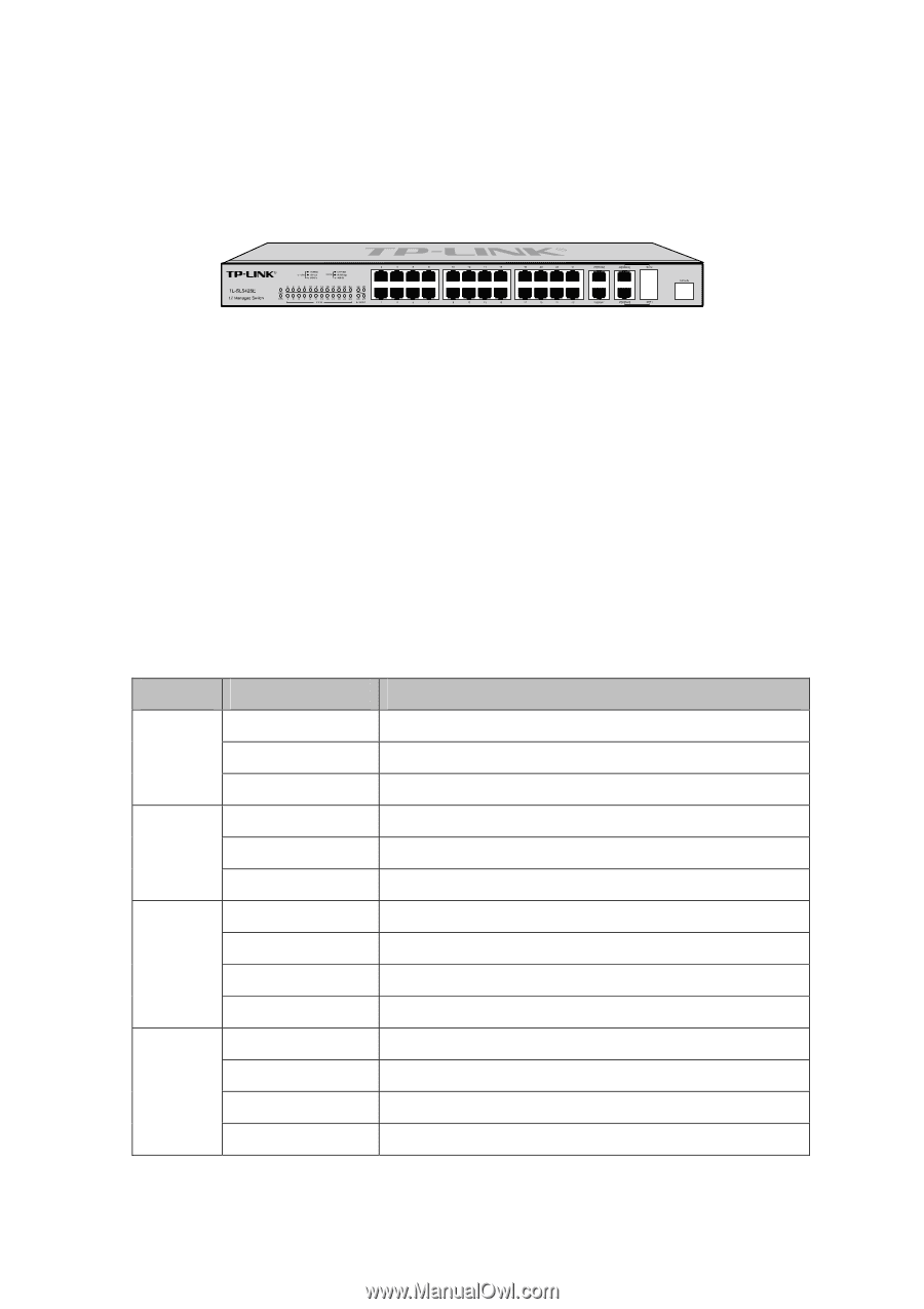
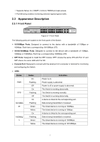
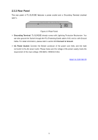
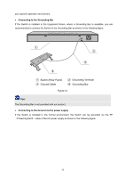
+ Supports Telnet, CLI, SNMP v1/v2c/v3, RMON and web access. + Port Mirroring enables monitoring selected ingress/egress traffic. 2.3 Appearance Description 2.3.1 Front Panel Figure 2-1 Front Panel The following parts are located on the front panel of the Switch: ¾ 10/100Mbps Ports: Designed to connect to the device with a bandwidth of 10Mbps or 100Mbps. Each has a corresponding 10/100Mbps LED. ¾ 10/100/1000Mbps Ports: Designed to connect to the device with a bandwidth of 10Mbps, 100Mbps or 1000Mbps. Each has a corresponding 1000Mbps LED. ¾ SFP Ports: Designed to install the SFP module. SFP1 shares the same LED with Port 27 and SFP shares the same LED with Port 28. ¾ Console Port: Designed to connect with the serial port of a computer or terminal for monitoring and configuring the Switch. ¾ LEDs Name PWR SYS 10/100Mb ps 1000Mbp s Status On Flashing Off On Flashing Off On Flashing Green Yellow On Flashing Green Yellow Indication Power is on. Power supply is abnormal. Power is off or power supply is abnormal. The Switch is working abnormally. The Switch is working normally. The Switch is working abnormally. A device is linked to the corresponding port. Data is being transmitted or received. The linked device is running at 100Mbps. The linked device is running at 10Mbps. A device is linked to the corresponding port. Data is being transmitted or received. The linked device is running at 1000Mbps. The linked device is running at 10/100Mbps. 7
-
 1
1 -
2
-
3
-
4
-
5
-
6
-
7
-
8
-
9
-
 10
10 -
 11
11 -
 12
12 -
 13
13 -
 14
14 -
 15
15 -
 16
16 -
 17
17 -
 18
18 -
 19
19 -
 20
20 -
21
-
22
-
23
-
24
-
25
-
26
-
27
-
28
-
29
-
30
-
31
-
32
-
33
-
34
-
35
-
36
-
37
-
38
-
39
-
40
-
41
-
42
-
43
-
44
-
45
-
46
-
47
-
48
-
49
-
50
-
51
-
52
-
53
-
54
-
55
-
56
-
57
-
58
-
59
-
60
-
61
-
62
-
63
-
64
-
65
-
66
-
67
-
68
-
69
-
70
-
71
-
72
-
73
-
74
-
75
-
76
-
77
-
78
-
79
-
80
-
81
-
82
-
83
-
84
-
85
-
86
-
87
-
88
-
89
-
90
-
91
-
92
-
93
-
94
-
95
-
96
-
97
-
98
-
99
-
100
-
101
-
102
-
103
-
104
-
105
-
106
-
107
-
108
-
109
-
110
-
111
-
112
-
113
-
114
-
115
-
116
-
117
-
118
-
119
-
120
-
121
-
122
-
123
-
124
-
125
-
126
-
127
-
128
-
129
-
130
-
131
-
132
-
133
-
134
-
135
-
136
-
137
-
138
-
139
-
140
-
141
-
142
-
143
-
144
-
145
-
146
-
147
-
148
-
149
-
150
-
151
-
152
-
153
-
154
-
155
-
156
-
157
-
158
-
159
-
160
-
161
-
162
-
163
-
164
-
165
-
166
-
167
-
168
-
169
-
170
-
171
-
172
-
173
-
174
-
175
-
176
-
177
-
178
-
179
-
180
-
181
-
182
-
183
-
184
-
185
-
186
-
187
-
188
-
189
-
190
-
191
-
192
-
193
-
194
-
195
-
196
-
197
-
198
-
199
-
200
-
201
-
202
-
203
-
204
-
205
-
206
-
207
-
208
-
209
-
210
-
211
-
212
-
213
-
214
-
215
-
216
-
217
-
218
-
219
-
220
-
221
-
222
-
223
-
224
-
225
-
226
-
227
-
228
-
229
-
230
-
231
-
232
-
233
-
234
-
235
-
236
-
237
-
238
-
239
-
240
-
241
-
242
-
243
-
244
-
245
-
246
-
247
-
248
-
249
-
250
 |
 |