Toshiba SD-V395 Service Manual - Page 33
Disassembly Instructions, REMOVAL OF MECHANICAL PARTS, AND P.C. BOARDS
 |
View all Toshiba SD-V395 manuals
Add to My Manuals
Save this manual to your list of manuals |
Page 33 highlights
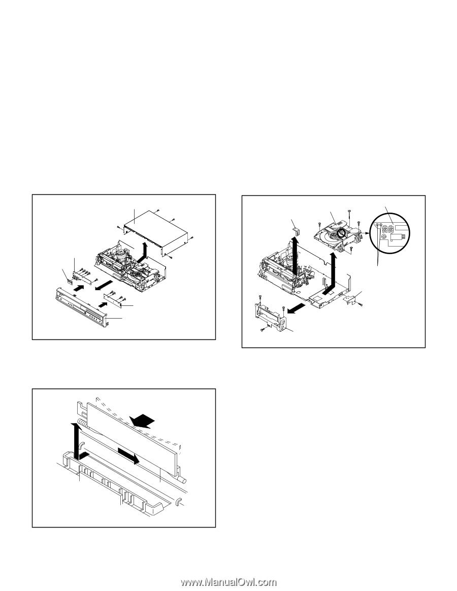
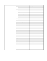
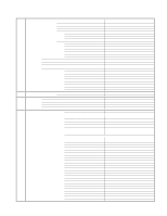
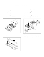
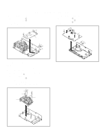
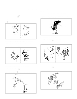
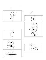
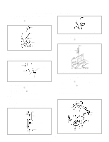
DISASSEMBLY INSTRUCTIONS 1. REMOVAL OF MECHANICAL PARTS AND P.C. BOARDS 1-1: TOP CABINET, FRONT CABINET AND OPERATION 1/2 PCB (Refer to Fig. 1-1) 1. Remove the 5 screws 1. 2. Remove the Top Cabinet in the direction of arrow (A). 3. Disconnect the following connectors: (CP651 and CP652). 4. Unlock the 8 supports 2. 5. Remove the Front Cabinet in the direction of arrow (B). 6. Remove the 9 screws 3. 7. Remove the Operation 1/2 PCB in the direction of arrow (C). 8. Remove the 3 Pin Shield. 1-3: DVD DECK (Refer to Fig. 1-3) 1. Make the short circuit on the position as shown Fig. 1-3 using a soldering. If you remove the DVD Deck with no soldering, the Laser may be damaged. 2. Unlock the support 1 and remove the Deck Top Holder in the direction of arrow (A). 3. Remove the 3 screws 2. 4. Remove the screw 3. 5. Disconnect the following connectors: (CP2601, CP2602 and CP2603). 6. Remove the DVD Deck in the direction of arrow (B). 7. Remove the 3 screws 4. 8. Remove the Front Angle in the direction of arrow (C). 9. Remove the screw 5. 10. Remove the DVD Angle. Top Cabinet 1 1 1 1 Operation 1 PCB (A) 3 Pin Shield 333 1 33 2 2 (C) 2 2 (C) (B) 333 3 2 Operation 2 PCB 2 2 Front Cabinet 2 Fig. 1-1 1-2: FLAP (Refer to Fig. 1-2) 1. Open Flap to 90˚ and flex in direction of arrow (A), at the same time slide in direction of arrow (B). 2. Then lift in direction of arrow (C). Deck Top Holder DVD Deck 2 3 2 Pick Up PCB 1 (A) 4 4 (C) 2 (B) Make the sort circuit using a soldering. DVD Angle 5 Front Angle 4 Fig. 1-3 NOTE When the installation of the DVD Deck, remove all the soldering on the short circuit position after the connection of Pick Up PCB and DVD PCB connector. (A) (C) (B) Flap Fig. 1-2 B1-1
-
 1
1 -
2
-
3
-
4
-
5
-
6
-
7
-
8
-
9
-
10
-
11
-
12
-
13
-
14
-
15
-
16
-
17
-
18
-
19
-
20
-
21
-
22
-
23
-
24
-
25
-
26
-
27
-
 28
28 -
 29
29 -
 30
30 -
 31
31 -
 32
32 -
 33
33 -
 34
34 -
 35
35 -
 36
36 -
 37
37 -
 38
38 -
39
-
40
-
41
-
42
-
43
-
44
-
45
-
46
-
47
-
48
-
49
-
50
-
51
-
52
-
53
-
54
-
55
-
56
-
57
-
58
-
59
-
60
-
61
-
62
-
63
-
64
-
65
-
66
-
67
-
68
-
69
-
70
-
71
-
72
-
73
-
74
-
75
-
76
-
77
-
78
-
79
-
80
-
81
-
82
-
83
-
84
-
85
-
86
-
87
-
88
-
89
-
90
-
91
-
92
-
93
-
94
-
95
-
96
-
97
-
98
-
99
-
100
-
101
-
102
-
103
-
104
-
105
-
106
-
107
-
108
-
109
-
110
-
111
-
112
-
113
-
114
-
115
-
116
-
117
-
118
-
119
-
120
-
121
-
122
-
123
-
124
-
125
-
126
-
127
-
128
-
129
-
130
-
131
-
132
-
133
-
134
-
135
-
136
-
137
-
138
-
139
-
140
-
141
-
142
-
143
-
144
 |
 |