Toshiba SD-V395 Service Manual - Page 43
: GEAR Refer to Fig. 3-9-A, Refer to Fig. 3-7-B, 8: RELAY PCB ASS'Y Refer to Fig. 3-8-A
 |
View all Toshiba SD-V395 manuals
Add to My Manuals
Save this manual to your list of manuals |
Page 43 highlights
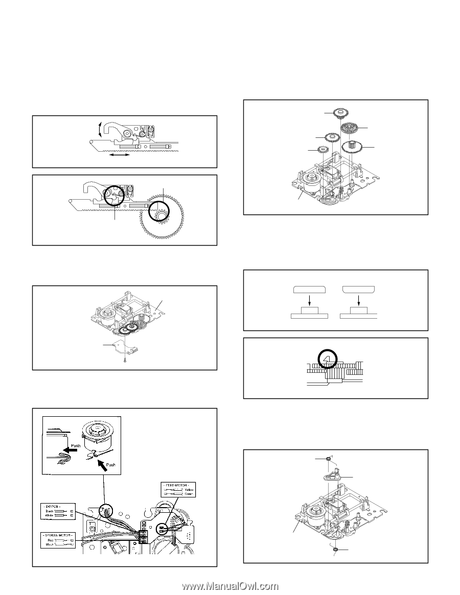
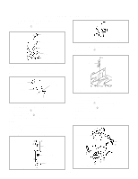
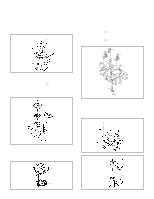
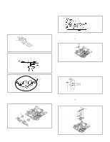
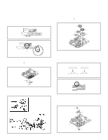
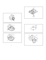
DISASSEMBLY INSTRUCTIONS NOTE 1. After the assembly of the Rack Feed, check if the Rack Feed 1/2 is moving smoothly. (Refer to Fig. 3-7-B) 2. In case of the Rack Feed Ass'y installation, install correctly as Fig. 3-7-C. 3-9: GEAR (Refer to Fig. 3-9-A) 1. Unlock the support 1. 2. Remove the Middle Gear 1/2/3, Idler Gear and Feed Gear. Middle Gear 2 Moving smoothly Moving smoothly Fig. 3-7-B Middle Gear 3 Idler Gear Middle Gear 1 Feed Gear Should not be engaged. Check the position of the Rack Feed Lever. Fig. 3-7-C 3-8: RELAY PCB ASS'Y (Refer to Fig. 3-8-A) 1. Remove the screw 1. 2. Remove the Relay PCB Ass'y. Main Chassis Ass'y Main Chassis Ass'y Fig. 3-9-A NOTE 1. In case of the Idler Gear installation, install correctly as Fig. 3-9-B. 2. When installing the Middle Gear 2, check if the Middle Gear 2 is locked correctly as Fig. 3-9-C. [OK] [NG] Idler Gear Idler Gear Relay PCB Ass'y • Screw Torque: 4 ± 0.5kgf•cm 1 Fig. 3-8-A NOTE 1. When installing the wire of the Relay PCB, install it correctly as Fig. 3-8-B. Idler Arm Idler Arm Check Lock Fig. 3-9-B Middle Gear 2 3-10: IDLER ARM (Refer to Fig. 3-10-A) 1. Remove the Idler Arm Spring. 2. Remove the Chassis Spring. 3. Remove the Idler Arm. Idler Arm Spring Idler Arm Fig. 3-9-C Fig. 3-8-B B3-3 Main Chassis Ass'y Chassis Spring Fig. 3-10-A
-
 1
1 -
2
-
3
-
4
-
5
-
6
-
7
-
8
-
9
-
10
-
11
-
12
-
13
-
14
-
15
-
16
-
17
-
18
-
19
-
20
-
21
-
22
-
23
-
24
-
25
-
26
-
27
-
28
-
29
-
30
-
31
-
32
-
33
-
34
-
35
-
36
-
37
-
 38
38 -
 39
39 -
 40
40 -
 41
41 -
 42
42 -
 43
43 -
 44
44 -
 45
45 -
 46
46 -
 47
47 -
 48
48 -
49
-
50
-
51
-
52
-
53
-
54
-
55
-
56
-
57
-
58
-
59
-
60
-
61
-
62
-
63
-
64
-
65
-
66
-
67
-
68
-
69
-
70
-
71
-
72
-
73
-
74
-
75
-
76
-
77
-
78
-
79
-
80
-
81
-
82
-
83
-
84
-
85
-
86
-
87
-
88
-
89
-
90
-
91
-
92
-
93
-
94
-
95
-
96
-
97
-
98
-
99
-
100
-
101
-
102
-
103
-
104
-
105
-
106
-
107
-
108
-
109
-
110
-
111
-
112
-
113
-
114
-
115
-
116
-
117
-
118
-
119
-
120
-
121
-
122
-
123
-
124
-
125
-
126
-
127
-
128
-
129
-
130
-
131
-
132
-
133
-
134
-
135
-
136
-
137
-
138
-
139
-
140
-
141
-
142
-
143
-
144
 |
 |