Toshiba SD-V395 Service Manual - Page 35
Removal Of Vcr Deck Parts, 3: Cassette Side L/r Refer To Fig. 2-3-a
 |
View all Toshiba SD-V395 manuals
Add to My Manuals
Save this manual to your list of manuals |
Page 35 highlights
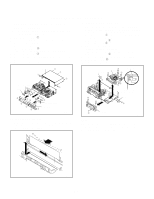
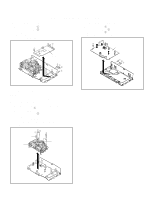
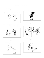
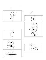
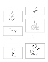
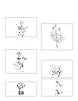
DISASSEMBLY INSTRUCTIONS 2. REMOVAL OF VCR DECK PARTS 2-1: TOP BRACKET (Refer to Fig. 2-1) 1. Extend the 2 supports 1. 2. Slide the 2 supports 2 and remove the Top Bracket. NOTE 1. After the installation of the Top Bracket, bend the support 1 so that the Top Bracket is fixed. Top Bracket 1 1 NOTE 1. In case of the Locker R installation, check if the one position of Fig. 2-3-B are correctly locked. 2. When you install the Cassette Side R, be sure to move the Locker R after installing. Locker R Cassette Side R Check if this position is locked. Top Bracket 2 Main Chassis 2 Main Chassis Fig. 2-1 2-2: CASSETTE HOLDER ASS'Y (Refer to Fig. 2-2) 1. Move the Cassette Holder Ass'y to the front side. 2. Push the Locker R to remove the Cassette Side R. 3. Remove the Cassette Side L. Main Chassis Cassette Side R Locker R Fig. 2-3-B 2-4: LINK UNIT (Refer to Fig. 2-4) 1. Set the Link Unit to the Eject position. 2. Unlock the support 1. 3. Remove the (A) side of the Link Unit first, then remove the (B) side. Main Chassis Link Unit Link Unit Cassette Side L Main Chassis Fig. 2-2 2-3: CASSETTE SIDE L/R (Refer to Fig. 2-3-A) 1. Remove the Locker Spring. 2. Unlock the 4 supports 1 and then remove the Cassette Side L/R. 3. Unlock the support 2 and then remove the Locker R. (A) (B) Link Unit Main Chassis Fig. 2-4 2-5: LINK LEVER/FLAP LEVER (Refer to Fig. 2-5) 1. Extend the support 1. 2. Remove the Link Lever. 3. Remove the Flap Lever. 1 1 2 Locker Spring Cassette Holder Flap Lever 1 Locker R 1 1 Link Lever Cassette Side R Cassette Side L Fig. 2-5 Fig. 2-3-A B2-1
-
 1
1 -
2
-
3
-
4
-
5
-
6
-
7
-
8
-
9
-
10
-
11
-
12
-
13
-
14
-
15
-
16
-
17
-
18
-
19
-
20
-
21
-
22
-
23
-
24
-
25
-
26
-
27
-
28
-
29
-
 30
30 -
 31
31 -
 32
32 -
 33
33 -
 34
34 -
 35
35 -
 36
36 -
 37
37 -
 38
38 -
 39
39 -
 40
40 -
41
-
42
-
43
-
44
-
45
-
46
-
47
-
48
-
49
-
50
-
51
-
52
-
53
-
54
-
55
-
56
-
57
-
58
-
59
-
60
-
61
-
62
-
63
-
64
-
65
-
66
-
67
-
68
-
69
-
70
-
71
-
72
-
73
-
74
-
75
-
76
-
77
-
78
-
79
-
80
-
81
-
82
-
83
-
84
-
85
-
86
-
87
-
88
-
89
-
90
-
91
-
92
-
93
-
94
-
95
-
96
-
97
-
98
-
99
-
100
-
101
-
102
-
103
-
104
-
105
-
106
-
107
-
108
-
109
-
110
-
111
-
112
-
113
-
114
-
115
-
116
-
117
-
118
-
119
-
120
-
121
-
122
-
123
-
124
-
125
-
126
-
127
-
128
-
129
-
130
-
131
-
132
-
133
-
134
-
135
-
136
-
137
-
138
-
139
-
140
-
141
-
142
-
143
-
144
 |
 |
