Toshiba SD-V395 Service Manual - Page 41
Removal Of Dvd Deck Parts, 2: Main Chassis Ass'y Refer To Fig. 3-2-a
 |
View all Toshiba SD-V395 manuals
Add to My Manuals
Save this manual to your list of manuals |
Page 41 highlights
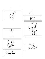
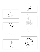
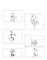
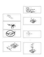
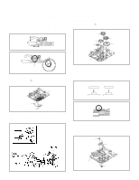
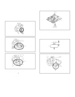
DISASSEMBLY INSTRUCTIONS 3. REMOVAL OF DVD DECK PARTS NOTE 1. Do not disassemble the DVD DECK PARTS except listed parts here. Minute adjustments are needed if the disassemble is done. If the repair is needed except listed parts, replace the DVD MECHA ASS'Y. 3-1: TRAY (Refer to Fig. 3-1-A) 1. Set the Tray opened. (Refer to the DISC REMOVAL METHOD AT NO POWER SUPPLY) 2. Unlock the support 1 and remove the Tray. 1 Tray Main Frame Ass'y Fig. 3-1-A NOTE 1. In case of the Tray installation, install them as the circled section of Fig. 3-1-B so that the each markers are met. Main Chassis Ass'y Rack Loading 1 23 6 4 Move it to the direction of the arrow. 5 Main Frame Ass'y 6 Check Lock 4 5 Fig. 3-2-B 3-3: RACK LOADING/MAIN GEAR/ RACK LOADING SPRING/ RACK L SPRING (Refer to Fig. 3-3) 1. Remove the Rack L Spring. 2. Press down the catcher 1 and slide the Rack Loading. 3. Remove the Rack Loading, Rack Loading Spring and Main Gear. Tray Rack Loading Spring Rack L Spring Rack Loading Main Gear Main Frame Ass'y Fig. 3-1-B 3-2: MAIN CHASSIS ASS'Y (Refer to Fig. 3-2-A) 1. Remove the Main Chassis Ass'y from the Insulator (R). 2. Unlock the support 1. 3. Remove the Main Chassis Ass'y. Insulator (R) (Green) 1 Main Frame Ass'y Main Frame Ass'y 1 Fig. 3-3 3-4: CLAMPER ASS'Y/INSULATOR(R)/LEVER SWITCH (Refer to Fig. 3-4-A) 1. Remove the screw 1. 2. Remove the Lever Switch. 3. Remove the 2 Insulator (R). 4. Press the Clamper and rotate the Clamper Plate clockwise, then unlock the 3 supports 2. 5. Remove the Clamper Plate, Clamper Magnet and Clamper. Insulator (R) (Green) Insulator (R) (Green) Clamper Plate Clamper Magnet Main Chassis Ass'y Fig. 3-2-A NOTE 1. In case of the Main Chassis Ass'y, install it from (1) to (6) in order. (Refer to Fig. 3-2-B) B3-1 Lever Switch 1 22 2 Clamper Main Frame Fig. 3-4-A
-
 1
1 -
2
-
3
-
4
-
5
-
6
-
7
-
8
-
9
-
10
-
11
-
12
-
13
-
14
-
15
-
16
-
17
-
18
-
19
-
20
-
21
-
22
-
23
-
24
-
25
-
26
-
27
-
28
-
29
-
30
-
31
-
32
-
33
-
34
-
35
-
 36
36 -
 37
37 -
 38
38 -
 39
39 -
 40
40 -
 41
41 -
 42
42 -
 43
43 -
 44
44 -
 45
45 -
 46
46 -
47
-
48
-
49
-
50
-
51
-
52
-
53
-
54
-
55
-
56
-
57
-
58
-
59
-
60
-
61
-
62
-
63
-
64
-
65
-
66
-
67
-
68
-
69
-
70
-
71
-
72
-
73
-
74
-
75
-
76
-
77
-
78
-
79
-
80
-
81
-
82
-
83
-
84
-
85
-
86
-
87
-
88
-
89
-
90
-
91
-
92
-
93
-
94
-
95
-
96
-
97
-
98
-
99
-
100
-
101
-
102
-
103
-
104
-
105
-
106
-
107
-
108
-
109
-
110
-
111
-
112
-
113
-
114
-
115
-
116
-
117
-
118
-
119
-
120
-
121
-
122
-
123
-
124
-
125
-
126
-
127
-
128
-
129
-
130
-
131
-
132
-
133
-
134
-
135
-
136
-
137
-
138
-
139
-
140
-
141
-
142
-
143
-
144
 |
 |
