Toshiba SD-V395 Service Manual - Page 39
: LOADING GEAR S/T UNIT Refer to Fig. 2-16-A, In case of the Pinch Roller Cam and Main Cam installa
 |
View all Toshiba SD-V395 manuals
Add to My Manuals
Save this manual to your list of manuals |
Page 39 highlights
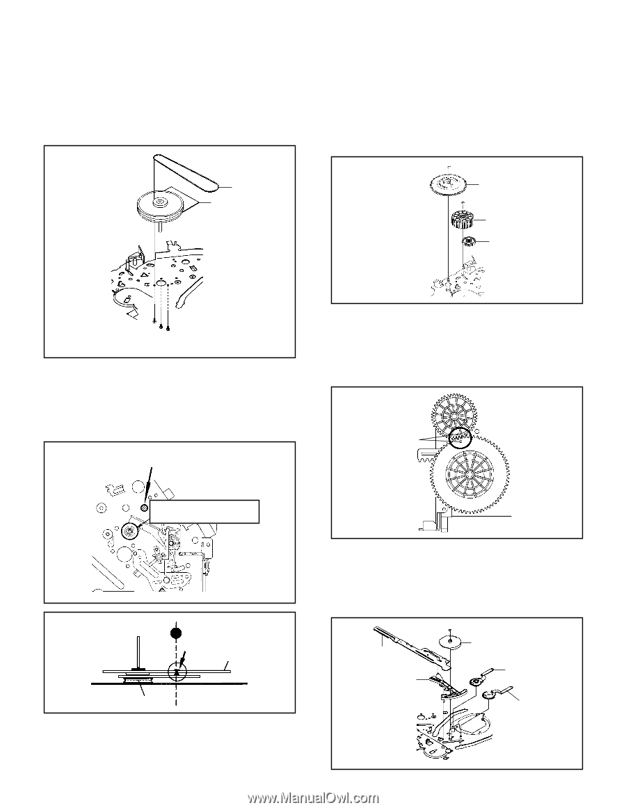
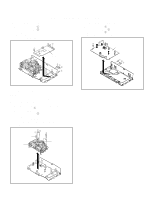
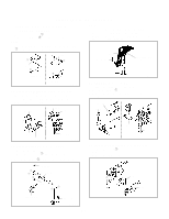
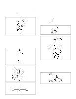
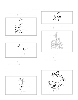
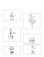
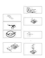
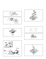
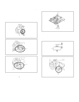
DISASSEMBLY INSTRUCTIONS 2-14: CAPSTAN DD UNIT (Refer to Fig. 2-14-A) 1. Remove the Capstan Belt. 2. Remove the 3 screws 1. 3. Remove the Capstan DD Unit. 2-15: MAIN CAM/PINCH ROLLER CAM/JOINT GEAR (Refer to Fig. 2-15-A) 1. Remove the E-Ring 1, then remove the Main Cam. 2. Remove the E-Ring 2, then remove the Pinch Roller Cam and Joint Gear. Capstan Belt Capstan DD Unit 1 Main Cam 2 Pinch Roller Cam Joint Gear 1 11 • Screw Torque: 4 ± 0.5kgf•cm Fig. 2-14-A NOTE 1. In case of the Capstan DD Unit installation, apply the silicon bond (TSE3843-W) on the position Fig. 2-14-B correctly. (If no silicon bond applied, abnormal noise will be heard on the deck operation.) (Refer to Fig. 2-14-B, C) Applied position of silicon bond Be careful not to apply the silicon bond to the Pinch Roller. Fig. 2-14-B Silicon Bond Main Chassis Capstan DD Unit Fig. 2-14-C Fig. 2-15-A NOTE 1. In case of the Pinch Roller Cam and Main Cam installa- tion, install them as the circled section of Fig. 2-15-B so that the each markers are met. (Refer to Fig. 2-15-B) And also can be seen the Main Chassis hole through the Main Cam maker hole. Pinch Roller Cam Marker Main Cam Fig. 2-15-B 2-16: LOADING GEAR S/T UNIT (Refer to Fig. 2-16-A) 1. Remove the E-Ring 1 and remove the Main Loading Gear. 2. Remove the Main Rod, Tension Lever, Loading Arm S Unit and Loading Arm T Unit. Main Rod Tension Lever 1 Main Loading Gear Loading Arm T Unit Loading Arm S Unit B2-5 Fig. 2-16-A
-
 1
1 -
2
-
3
-
4
-
5
-
6
-
7
-
8
-
9
-
10
-
11
-
12
-
13
-
14
-
15
-
16
-
17
-
18
-
19
-
20
-
21
-
22
-
23
-
24
-
25
-
26
-
27
-
28
-
29
-
30
-
31
-
32
-
33
-
 34
34 -
 35
35 -
 36
36 -
 37
37 -
 38
38 -
 39
39 -
 40
40 -
 41
41 -
 42
42 -
 43
43 -
 44
44 -
45
-
46
-
47
-
48
-
49
-
50
-
51
-
52
-
53
-
54
-
55
-
56
-
57
-
58
-
59
-
60
-
61
-
62
-
63
-
64
-
65
-
66
-
67
-
68
-
69
-
70
-
71
-
72
-
73
-
74
-
75
-
76
-
77
-
78
-
79
-
80
-
81
-
82
-
83
-
84
-
85
-
86
-
87
-
88
-
89
-
90
-
91
-
92
-
93
-
94
-
95
-
96
-
97
-
98
-
99
-
100
-
101
-
102
-
103
-
104
-
105
-
106
-
107
-
108
-
109
-
110
-
111
-
112
-
113
-
114
-
115
-
116
-
117
-
118
-
119
-
120
-
121
-
122
-
123
-
124
-
125
-
126
-
127
-
128
-
129
-
130
-
131
-
132
-
133
-
134
-
135
-
136
-
137
-
138
-
139
-
140
-
141
-
142
-
143
-
144
 |
 |