Toshiba SD-V395 Service Manual - Page 34
: VCR PCB Refer to Fig. 1-6, Remove the AC Head Cover and VCR Deck in
 |
View all Toshiba SD-V395 manuals
Add to My Manuals
Save this manual to your list of manuals |
Page 34 highlights
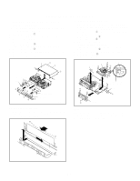
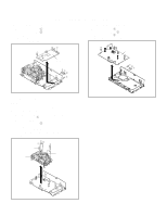
DISASSEMBLY INSTRUCTIONS 1-4: DVD PCB (Refer to Fig. 1-4) 1. Remove the 3 screws 1. 2. Remove the 4 screws 2. 3. Disconnect the following connectors: (CP4002 and CP8102). 4. Remove the DVD PCB in the direction of arrow. 1-6: VCR PCB (Refer to Fig. 1-6) 1. Remove the screw 1. 2. Remove the 2 screws 2. 3. Remove the screw 3. 4. Remove the VCR PCB in the direction of arrow. 1 1 1 DVD PCB 22 2 2 3 VCR PCB 1 2 2 Fig. 1-4 1-5: VCR DECK (Refer to Fig. 1-5) NOTE Do not remove the cable at the FE Head section. The FE Head may be damaged if you remove the cable by force. 1. Move the Cassette Holder Ass'y to the back side. 2. Remove the screw 1. 3. Remove the FE Head. 4. Remove the 3 screws 2. 5. Disconnect the following connectors: (CP101, CP102, and CP3001). 6. Remove the AC Head Cover and VCR Deck in the direction of arrow. 22 1 2 FE Head VCR Deck AC Head Cover Fig. 1-6 Fig. 1-5 B1-2
-
 1
1 -
2
-
3
-
4
-
5
-
6
-
7
-
8
-
9
-
10
-
11
-
12
-
13
-
14
-
15
-
16
-
17
-
18
-
19
-
20
-
21
-
22
-
23
-
24
-
25
-
26
-
27
-
28
-
 29
29 -
 30
30 -
 31
31 -
 32
32 -
 33
33 -
 34
34 -
 35
35 -
 36
36 -
 37
37 -
 38
38 -
 39
39 -
40
-
41
-
42
-
43
-
44
-
45
-
46
-
47
-
48
-
49
-
50
-
51
-
52
-
53
-
54
-
55
-
56
-
57
-
58
-
59
-
60
-
61
-
62
-
63
-
64
-
65
-
66
-
67
-
68
-
69
-
70
-
71
-
72
-
73
-
74
-
75
-
76
-
77
-
78
-
79
-
80
-
81
-
82
-
83
-
84
-
85
-
86
-
87
-
88
-
89
-
90
-
91
-
92
-
93
-
94
-
95
-
96
-
97
-
98
-
99
-
100
-
101
-
102
-
103
-
104
-
105
-
106
-
107
-
108
-
109
-
110
-
111
-
112
-
113
-
114
-
115
-
116
-
117
-
118
-
119
-
120
-
121
-
122
-
123
-
124
-
125
-
126
-
127
-
128
-
129
-
130
-
131
-
132
-
133
-
134
-
135
-
136
-
137
-
138
-
139
-
140
-
141
-
142
-
143
-
144
 |
 |
