Toshiba SD-V395 Service Manual - Page 58
CONFIRMATION AND ADJUSTMENT OF AUDIO, Playback the VHS Alignment Tape Monoscope of ST-N5
 |
View all Toshiba SD-V395 manuals
Add to My Manuals
Save this manual to your list of manuals |
Page 58 highlights
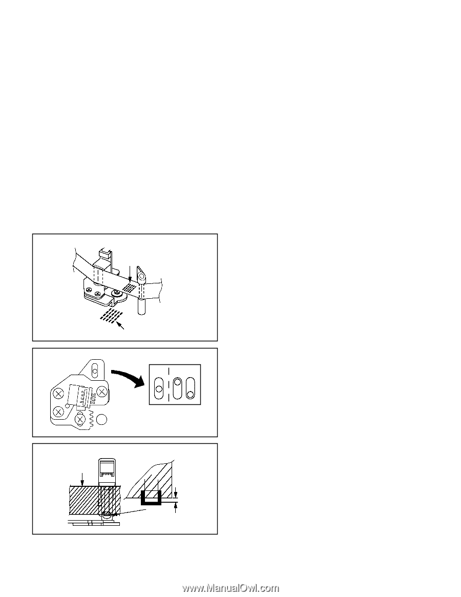
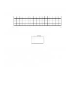
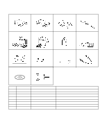
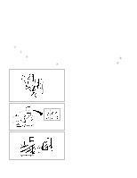
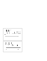
MECHANICAL ADJUSTMENTS 2-2: CONFIRMATION AND ADJUSTMENT OF AUDIO/ CONTROL HEAD When the Tape Running Mechanism does not work well, adjust the following items. 1. Playback the VHS Alignment Tape (Monoscope of ST-N5 MODE2). 2. Confirm that the reflected picture of stamp mark is appeared on the tape prior to P4 Cap as shown in Fig. 22-A. a) When the reflected picture is distorted, turn the screw 1 clockwise until the distortion is disappeared. b) When the reflected picture is not distorted, turn the screw 1 counterclockwise until little distortion is appeared, then adjust the a). 3. Turn the screw 2 to set the audio level to maximum. 4. Confirm that the bottom of the Audio/ Control Head and the bottom of the tape is shown in Fig. 2-2-C. c) When the height is not correct, turn the screw 3 to adjust the height. Then, adjust the 1~3 again. Audio/Control Head Reflected picture of Stamp Mark P4 Cap 2-3: TAPE RUNNING ADJUSTMENT (X VALUE ADJUSTMENT) 1. Confirm and adjust the height of the Reel Disk. (Refer to item 1-1) 2. Confirm and adjust the position of the Tension Post. (Refer to item 1-2) 3. Adjust the Guide Roller. (Refer to item 2-1) 4. Confirm and adjust the Audio/Control Head. (Refer to item 2-2) 5. Connect CH-1 of the oscilloscope to TP3002 and CH-2 to TP101. 6. Playback the VHS Alignment Tape (Monoscope of ST-N5 MODE2). 7. Press and hold the ATR button on the remote control more than 2 seconds to set tracking to center. 8. Set the X Value adjustment driver (JG153) to the 4 of Fig. 2-2-B. Adjust X value so that the envelope waveform output becomes maximum. Then, check if the 5 section of Fig. 2-2-B is on the center position (or rather to the cylinder side). In case of the envelope maximum at the difference position from the center, adjust the matching of picture and sound again. Audio/Control Head 5 Stamp Mark Fig. 2-2-A [OK] [NG] 3 1 2 4 Fig. 2-2-B Audio/Control Head Tape 0.25±0.05mm Fig. 2-2-C D2-3
-
 1
1 -
2
-
3
-
4
-
5
-
6
-
7
-
8
-
9
-
10
-
11
-
12
-
13
-
14
-
15
-
16
-
17
-
18
-
19
-
20
-
21
-
22
-
23
-
24
-
25
-
26
-
27
-
28
-
29
-
30
-
31
-
32
-
33
-
34
-
35
-
36
-
37
-
38
-
39
-
40
-
41
-
42
-
43
-
44
-
45
-
46
-
47
-
48
-
49
-
50
-
51
-
52
-
 53
53 -
 54
54 -
 55
55 -
 56
56 -
 57
57 -
 58
58 -
 59
59 -
 60
60 -
 61
61 -
 62
62 -
 63
63 -
64
-
65
-
66
-
67
-
68
-
69
-
70
-
71
-
72
-
73
-
74
-
75
-
76
-
77
-
78
-
79
-
80
-
81
-
82
-
83
-
84
-
85
-
86
-
87
-
88
-
89
-
90
-
91
-
92
-
93
-
94
-
95
-
96
-
97
-
98
-
99
-
100
-
101
-
102
-
103
-
104
-
105
-
106
-
107
-
108
-
109
-
110
-
111
-
112
-
113
-
114
-
115
-
116
-
117
-
118
-
119
-
120
-
121
-
122
-
123
-
124
-
125
-
126
-
127
-
128
-
129
-
130
-
131
-
132
-
133
-
134
-
135
-
136
-
137
-
138
-
139
-
140
-
141
-
142
-
143
-
144
 |
 |