Toshiba SD-V395 Service Manual - Page 42
: TRAVERSE HOLDER/INSULATOR F, Refer to Fig. 3-5-A, 6: SWITCH PCB ASS'Y Refer to Fig. 3-6-A
 |
View all Toshiba SD-V395 manuals
Add to My Manuals
Save this manual to your list of manuals |
Page 42 highlights
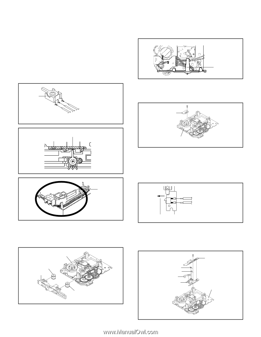
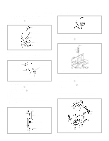
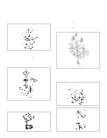
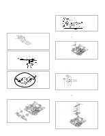
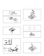
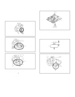
DISASSEMBLY INSTRUCTIONS NOTE 1. When installing the Clamper Magnet, install it with the green face up. 2. When installing the wire of the Lever Switch, install it correctly as Fig. 3-4-B. 3. When installing the Lever Switch, install it correctly as Fig. 3-4-C. 4. In case of the Lever Switch installation, hook the wire on the Main Frame as shown Fig. 3-4-D. Lever Switch Main Chassis Ass'y Traverse Holder Fig. 3-5-B 3-6: SWITCH PCB ASS'Y (Refer to Fig. 3-6-A) 1. Remove the screw 1. 2. Remove the Switch PCB Ass'y. Red White Blue From DVD PCB Fig. 3-4-B 1 Switch PCB Ass'y The Lever should be position between A and B. Rack Loading A B Fig. 3-4-C Main Chassis Ass'y • Screw Torque: 4 ± 0.5kgf•cm Fig. 3-6-A NOTE 1. When installing the wire of the Switch PCB, install it correctly as Fig. 3-6-B. 2. When installing the wire of the Switch PCB, while pressing it in the direction of the arrow as shown Fig. 3-6B, then install it. Lever Switch Switch PCB Ass'y Black From Relay PCB White 3-5: TRAVERSE HOLDER/INSULATOR (F) (Refer to Fig. 3-5-A) 1. Remove the Traverse Holder. 2. Remove the 2 Insulator (F). Fig. 3-4-D Main Chassis Ass'y Fig. 3-6-B 3-7: RACK FEED ASS'Y (Refer to Fig. 3-7-A) 1. Remove the screw 1. 2. Remove the Rack Feed 1/2 Spring, Rack Feed 1/2 and Rack Feed Lever. Main Chassis Ass'y Insulator (F) (Black) Traverse Holder Insulator (F) (Black) Fig. 3-5-A 1 Rack Feed 1 Spring Rack Feed 2 Spring Rack Feed Lever Rack Feed 1 Rack Feed 2 Main Chassis Ass'y NOTE 1. After the installing of the Traverse Holder, check if the wire is like Fig. 3-5-B. B3-2 • Screw Torque: 3.5 ± 0.5kgf•cm Fig. 3-7-A
-
 1
1 -
2
-
3
-
4
-
5
-
6
-
7
-
8
-
9
-
10
-
11
-
12
-
13
-
14
-
15
-
16
-
17
-
18
-
19
-
20
-
21
-
22
-
23
-
24
-
25
-
26
-
27
-
28
-
29
-
30
-
31
-
32
-
33
-
34
-
35
-
36
-
 37
37 -
 38
38 -
 39
39 -
 40
40 -
 41
41 -
 42
42 -
 43
43 -
 44
44 -
 45
45 -
 46
46 -
 47
47 -
48
-
49
-
50
-
51
-
52
-
53
-
54
-
55
-
56
-
57
-
58
-
59
-
60
-
61
-
62
-
63
-
64
-
65
-
66
-
67
-
68
-
69
-
70
-
71
-
72
-
73
-
74
-
75
-
76
-
77
-
78
-
79
-
80
-
81
-
82
-
83
-
84
-
85
-
86
-
87
-
88
-
89
-
90
-
91
-
92
-
93
-
94
-
95
-
96
-
97
-
98
-
99
-
100
-
101
-
102
-
103
-
104
-
105
-
106
-
107
-
108
-
109
-
110
-
111
-
112
-
113
-
114
-
115
-
116
-
117
-
118
-
119
-
120
-
121
-
122
-
123
-
124
-
125
-
126
-
127
-
128
-
129
-
130
-
131
-
132
-
133
-
134
-
135
-
136
-
137
-
138
-
139
-
140
-
141
-
142
-
143
-
144
 |
 |