Toshiba SD-V395 Service Manual - Page 40
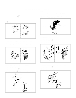
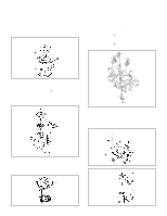
When you install the Loading Arm S Unit, Loading Arm T, UNIT/P4 CAP Refer to Fig. 2-18-A
 |
View all Toshiba SD-V395 manuals
Add to My Manuals
Save this manual to your list of manuals |
Page 40 highlights
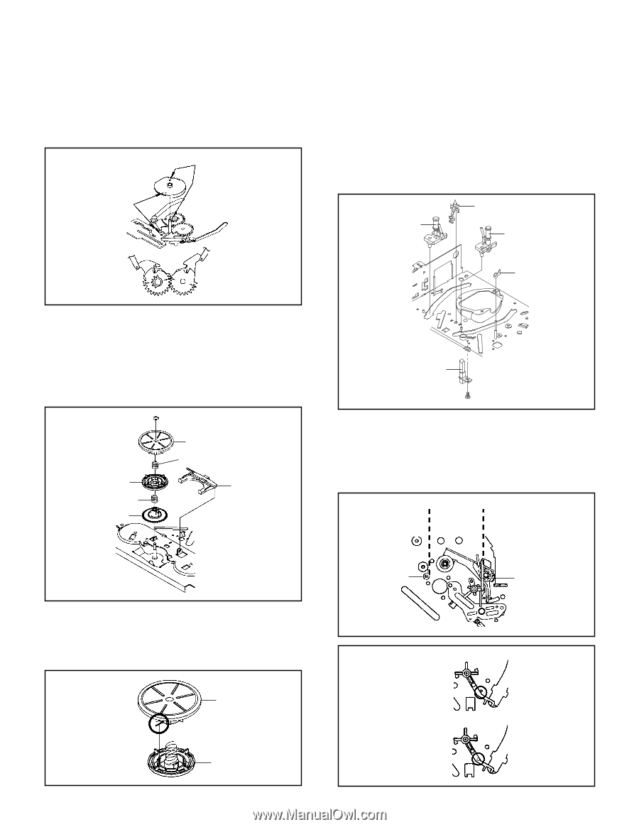
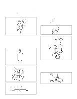
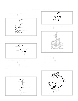
DISASSEMBLY INSTRUCTIONS NOTE 1. When you install the Loading Arm S Unit, Loading Arm T Unit and Main Loading Gear, align each marker. (Refer to Fig. 2-16-B) Marker Main Loading Gear Marker 2-18: CASSETTE GUIDE POST/INCLINED BASE S/T UNIT/P4 CAP (Refer to Fig. 2-18-A) 1. Remove the P4 Cap. 2. Unlock the support 1 and remove the Cassette Guide Post. 3. Remove the Inclined Base S/T Unit. 4. Remove the screw 2. 5. Remove the LED Reflector. 1 Inclined Base S Unit Cassette Guide Post Inclined Base T Unit Loading Arm T Unit Loading Arm S Unit Fig. 2-16-B 2-17: CLUTCH ASS'Y/RING SPRING/CLUTCH LEVER/ CLUTCH GEAR (Refer to Fig. 2-17-A) 1. Remove the Polyslider Washer 1. 2. Remove the Clutch Ass'y and Ring Spring. 3. Remove the Clutch Lever. 4. Remove the Coupling Gear, Coupling Spring and Clutch Gear. 1 Coupling Gear Coupling Spring Clutch Gear Clutch Ass'y Ring Spring Clutch Lever P4 Cap LED Reflector 2 • Screw Torque: 5 ± 0.5kgf•cm Fig. 2-18-A NOTE 1. Do not touch the roller of Guide Roller. 2. In case of the P4 Cap installation, install it with parallel for "A" and "B" of Fig. 2-18-B. 3. In case of the Cassette Guide Post installation, install correctly as the circled section of Fig. 2-18-C. "A" "B" Fig. 2-17-A NOTE 1. In case of the Clutch Ass'y installation, install it with inserting the spring of the Clutch Ass'y into the dent of the Coupling Gear. (Refer to Fig. 2-17-B) Clutch Ass'y Coupling Gear Fig. 2-17-B B2-6 P4 Cap [OK] Cassette Guide Post [NG] Cassette Guide Post Cassette Opener Fig. 2-18-B Fig. 2-18-C
-
 1
1 -
2
-
3
-
4
-
5
-
6
-
7
-
8
-
9
-
10
-
11
-
12
-
13
-
14
-
15
-
16
-
17
-
18
-
19
-
20
-
21
-
22
-
23
-
24
-
25
-
26
-
27
-
28
-
29
-
30
-
31
-
32
-
33
-
34
-
 35
35 -
 36
36 -
 37
37 -
 38
38 -
 39
39 -
 40
40 -
 41
41 -
 42
42 -
 43
43 -
 44
44 -
 45
45 -
46
-
47
-
48
-
49
-
50
-
51
-
52
-
53
-
54
-
55
-
56
-
57
-
58
-
59
-
60
-
61
-
62
-
63
-
64
-
65
-
66
-
67
-
68
-
69
-
70
-
71
-
72
-
73
-
74
-
75
-
76
-
77
-
78
-
79
-
80
-
81
-
82
-
83
-
84
-
85
-
86
-
87
-
88
-
89
-
90
-
91
-
92
-
93
-
94
-
95
-
96
-
97
-
98
-
99
-
100
-
101
-
102
-
103
-
104
-
105
-
106
-
107
-
108
-
109
-
110
-
111
-
112
-
113
-
114
-
115
-
116
-
117
-
118
-
119
-
120
-
121
-
122
-
123
-
124
-
125
-
126
-
127
-
128
-
129
-
130
-
131
-
132
-
133
-
134
-
135
-
136
-
137
-
138
-
139
-
140
-
141
-
142
-
143
-
144
 |
 |