Yamaha 01V96i Owner's Manual - Page 16
Rear Panel, PHANTOM +48V, AD Output - digital console
 |
View all Yamaha 01V96i manuals
Add to My Manuals
Save this manual to your list of manuals |
Page 16 highlights
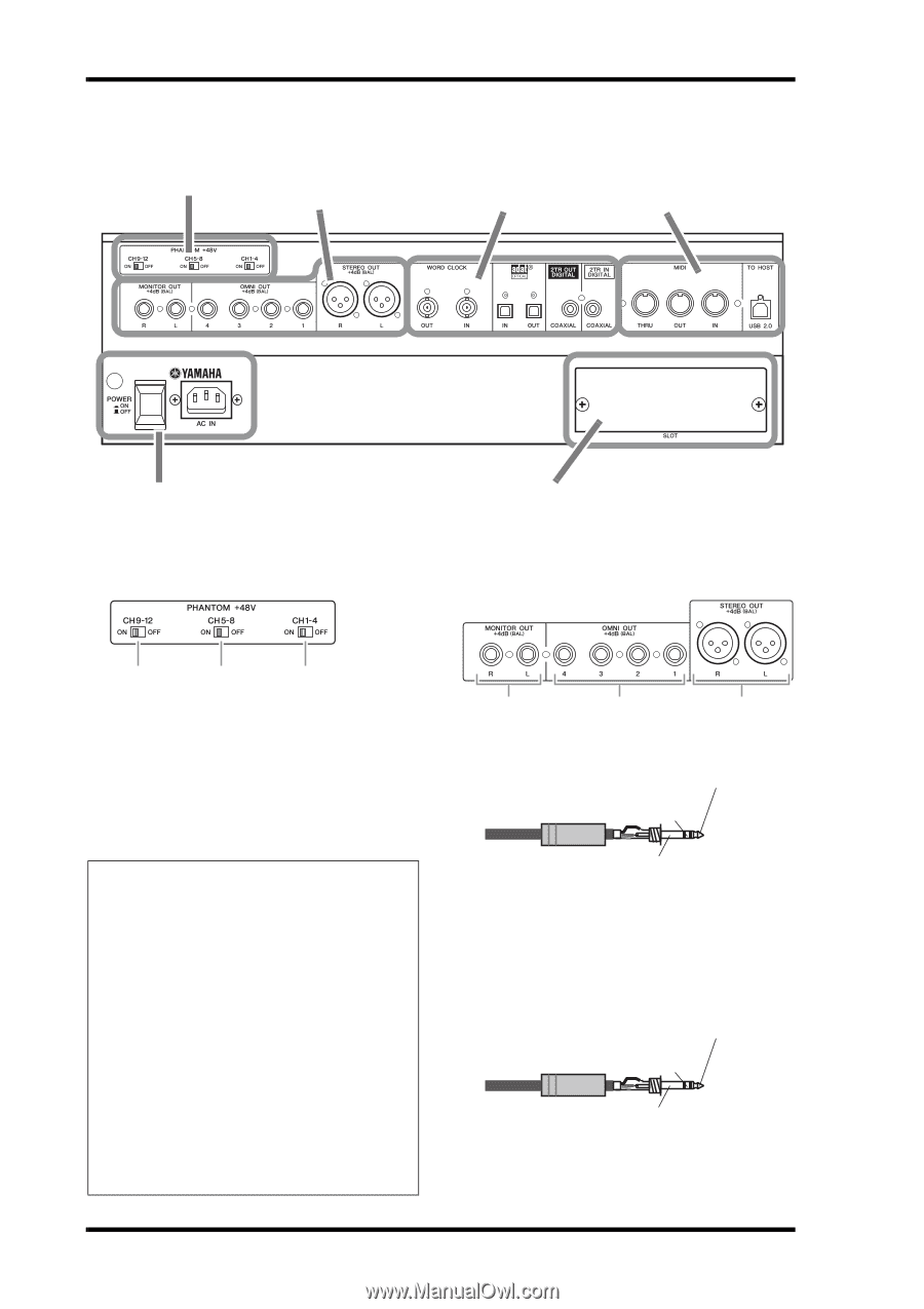
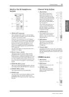
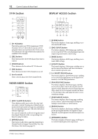
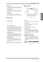
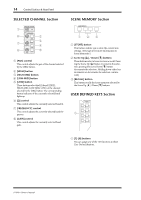
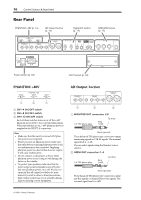
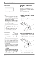
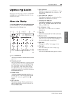
16 Control Surface & Rear Panel Rear Panel PHANTOM +48V (p. 16) AD Output Section (p. 16) Digital I/O Section (p. 17) MIDI/USB Section (p. 17) Power Section (p. 18) PHANTOM +48V SLOT Section (p. 18) AD Output Section 3 2 1 1 CH1-4 ON/OFF switch 2 CH5-8 ON/OFF switch 3 CH9-12 ON/OFF switch Each of these switches turns on or off the +48V phantom power feed to four corresponding inputs. When the switches are on, +48V phantom power is supplied to the INPUT A connectors. Note: • Make sure that this switch is turned off if phan- tom power is not required. • Before you turn on phantom power, make sure that only devices requiring phantom power (such as condenser mics) are connected. Supplying phantom power to a device that does not require it will cause malfunctions. • Do not connect or disconnect a device while phantom power is on. Doing so will damage the device or the console. • To protect your speakers, make sure that the power amps (powered speakers) are off before you turn phantom power on or off. We also recommend that all output level faders be minimized. If you fail to observe these precautions, high volume output may occur, possibly damaging your hearing or your equipment. 1 2 3 1 MONITOR OUT connectors L/R 1/4" TRS phone plug Ring (cold) Tip (hot) Sleeve (ground) These balanced TRS phone-type connectors output monitoring signals or 2TR IN signals. The nominal signal level is +4 dB. You can select signals using the Monitor Source selector. 2 OMNI OUT connectors 1-4 1/4" TRS phone plug Ring (cold) Tip (hot) Sleeve (ground) These balanced TRS phone-type connectors output any Bus signals or channel Direct Out signals. The nominal signal level is +4 dB. 01V96i-Owner's Manual
-
 1
1 -
2
-
3
-
4
-
5
-
6
-
7
-
8
-
9
-
10
-
 11
11 -
 12
12 -
 13
13 -
 14
14 -
 15
15 -
 16
16 -
 17
17 -
 18
18 -
 19
19 -
 20
20 -
 21
21 -
22
-
23
-
24
-
25
-
26
-
27
-
28
-
29
-
30
-
31
-
32
-
33
-
34
-
35
-
36
-
37
-
38
-
39
-
40
-
41
-
42
-
43
-
44
-
45
-
46
-
47
-
48
-
49
-
50
-
51
-
52
-
53
-
54
-
55
-
56
-
57
-
58
-
59
-
60
-
61
-
62
-
63
-
64
-
65
-
66
-
67
-
68
-
69
-
70
-
71
 |
 |