Yamaha 01V96i Owner's Manual - Page 22
Selecting Channels, Selecting Fader Modes, REO [SEL] button.
 |
View all Yamaha 01V96i manuals
Add to My Manuals
Save this manual to your list of manuals |
Page 22 highlights
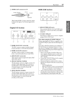
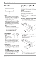
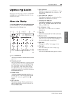
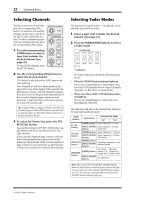
22 Operating Basics Selecting Channels To select a channel on the 01V96i, press the corresponding [SEL] button. To adjust the Pan and EQ settings, use the rotary controls in the SELECTED CHANNEL section. To select a channel on pages that cover multiple channels, press the corresponding [SEL] button. Q HIGH 1. Press the corresponding LAYER button to select a layer that includes the desired channel (see page 21). To select ST IN channels, press the [ST IN] button. HIGH-MID FREQUENCY LOW-MID GAIN LOW 2. Use the corresponding [SEL] button to select the desired channel. The channel is selected and the [SEL] button indicator lights up. The Channel's ID and short name appear in the upper-left corner of the display. If the currently-displayed page contains a relevant channel parameter, the cursor moves to that parameter automatically. If the currently-displayed page contains no such parameter, a page that does contain such a parameter is selected automatically. Tip: For paired Input or Output Channels, the channel for which you pressed the [SEL] button is selected, and its indicator lights up. The [SEL] button indicator of the paired partner flashes. 3. To select the Stereo Out, press the STE- REO [SEL] button. Repeatedly pressing the STEREO [SEL] button toggles between the Stereo Out left and Stereo Out right channels. If the currently-displayed page contains a relevant Stereo Out parameter, the cursor moves to that parameter automatically. If the currently-displayed page contains no such parameter, a page that does contain such a parameter is selected automatically. Selecting Fader Modes The function of channel faders (1-16) depends on the selected Layer and Fader mode. 1. Select a layer that includes the desired channel (see page 21). 2. Press the FADER MODE buttons to select a Fader mode. FADER MODE AUX 1 AUX 2 AUX 3 AUX 4 AUX 5 AUX 6 AUX 7 AUX 8 HOME (METER) The button indicators identify the following Fader modes: • When the [HOME] button indicator lights up: You can use channel faders to control Input Channels and ST IN Channel levels or Output Channels (Aux Out 1-8, Bus Out 1-8) master levels. • When one of the [AUX1]-[AUX8] button indicators light up: You can use channel faders to control the corresponding Aux Send level. The following table shows the channel fader functions for each Layer and Fader mode. LAYER buttons Fader Mode Channel Strip Fader 1-8 9-16 [1-16] button [HOME] button Input Channel 1-16 level [AUX1]-[AUX8] Input Channel 1-16 Aux buttons Send level [17-32] button [HOME] button [AUX1]-[AUX8] buttons [HOME] button [REMOTE] button [AUX1]-[AUX8] buttons [HOME] button [MASTER] button [AUX1]-[AUX8] buttons Input Channel 17-32 level Input Channel 17-32 Aux Send level Operation depends on the selected target. Aux Send Bus Out master 1-8 master1-8 output level output level No operation Note: You cannot select the [AUX1]-[AUX8] buttons while the Master layer is selected. If you switch to the Master layer while one of the [AUX1]-[AUX8] button indicators is lit, the indicator automatically turns off and the [HOME] button indicator lights up. 01V96i-Owner's Manual
-
 1
1 -
2
-
3
-
4
-
5
-
6
-
7
-
8
-
9
-
10
-
11
-
12
-
13
-
14
-
15
-
16
-
 17
17 -
 18
18 -
 19
19 -
 20
20 -
 21
21 -
 22
22 -
 23
23 -
 24
24 -
 25
25 -
 26
26 -
 27
27 -
28
-
29
-
30
-
31
-
32
-
33
-
34
-
35
-
36
-
37
-
38
-
39
-
40
-
41
-
42
-
43
-
44
-
45
-
46
-
47
-
48
-
49
-
50
-
51
-
52
-
53
-
54
-
55
-
56
-
57
-
58
-
59
-
60
-
61
-
62
-
63
-
64
-
65
-
66
-
67
-
68
-
69
-
70
-
71
 |
 |
