Yamaha 01V96i Owner's Manual - Page 31
Tutorial, Input and Output Patching - mixer
 |
View all Yamaha 01V96i manuals
Add to My Manuals
Save this manual to your list of manuals |
Page 31 highlights
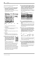
Tutorial 31 Tutorial This chapter describes operations on the 01V96i, organized according to their purpose. Input and Output Patching The 01V96i allows you to freely connect external input/output connectors to the inputs and outputs of the internal mixer. The procedure is as follows. 3. Press [ENTER] to confirm the change. Note: Alternatively, you can move the cursor to the input channel's parameter box and then press [ENTER], and make a selection in the "PATCH SELECT" box. In this case, select the desired input connector and channel number, and press [INC] to confirm the change. Input Patching 1. Press the DISPLAY ACCESS [PATCH] but- ton repeatedly until the Patch | In Patch page page appears. Output Patching 1. Press the [PATCH] button repeatedly until the Patch | Out Patch page appears. By default, signals from the instruments or mics connected to INPUT connectors 1-16 are sent to Input Channels 1-16. Input signals from the ADAT IN connector are sent to Input Channels 17-24, and input signals from the slot are sent to Input Channels 25-32. 2. Move the cursor to the parameter box of the input channel for which you want to change the assignment, and use the Parameter wheel or the [INC]/[DEC] buttons to modify the patching. By default, the patching will be as shown in the illustration. 2. As you did when making input patch set- tings, move the cursor to the parameter box of the output channel, and use the Parameter wheel or the [INC]/[DEC] buttons to modify the patching. 3. Press [ENTER] to confirm the change. Tutorial 01V96i-Owner's Manual
-
 1
1 -
2
-
3
-
4
-
5
-
6
-
7
-
8
-
9
-
10
-
11
-
12
-
13
-
14
-
15
-
16
-
17
-
18
-
19
-
20
-
21
-
22
-
23
-
24
-
25
-
 26
26 -
 27
27 -
 28
28 -
 29
29 -
 30
30 -
 31
31 -
 32
32 -
 33
33 -
 34
34 -
 35
35 -
 36
36 -
37
-
38
-
39
-
40
-
41
-
42
-
43
-
44
-
45
-
46
-
47
-
48
-
49
-
50
-
51
-
52
-
53
-
54
-
55
-
56
-
57
-
58
-
59
-
60
-
61
-
62
-
63
-
64
-
65
-
66
-
67
-
68
-
69
-
70
-
71
 |
 |
