Yamaha 01V96i Owner's Manual - Page 32
Setting the Input Levels - tutorial
 |
View all Yamaha 01V96i manuals
Add to My Manuals
Save this manual to your list of manuals |
Page 32 highlights
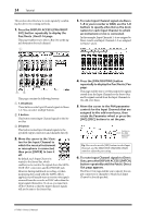
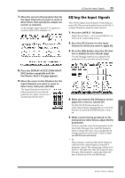
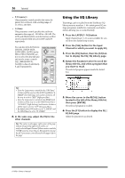
32 Tutorial Setting the Input Levels The explanation here provides an example of adjusting the input level of the signals from instruments or mics connected to INPUT connectors, with the input patching in the default state. 1. While the musicians play the instruments or devices connected to the INPUT connector, adjust each [PAD] and [GAIN] so that [PEAK] flickers briefly when the maximum volume occurs.. Note: The [GAIN] controls adjust the analog input sensitivity. To make a high-quality recording with a wide dynamic range and little noise, set the [GAIN] controls as high as possible while avoiding clipping. 2. Press the LAYER [1-16] button. Input Channel Layer 1-16 is now available for control from the channel strip section. Note: Since the fader and [ON] button positions of each layer are memorized, those positions for the corresponding layer are restored when you switch to that layer. 3. Press the FADER MODE [HOME] button, then press the [F1] button to display the Meter | CH1-32 page. Meter pages are the start point for mixing and recording. They display channel input and output levels, and compressor and gate gain reduction amounts. The CH1-32 page enables you to view Input Channel 1-32 levels and compressor and gate gain reduction amounts. 1 2 4. Make sure that the LEVEL button (1) is turned on in the METER MODE section. The METER MODE section enables you to select the type of signals displayed on the meters. If any button other than the LEVEL button is turned on, move the cursor to the LEVEL button, then press [ENTER]. 5. Move the cursor to the POSITION param- eter box (2) to the right of the LEVEL button, rotate the Parameter wheel or press the [INC]/[DEC] buttons to select "POST FADER," then press [ENTER]. The POSITION parameter indicates the metering position. When "POST FADER" is selected, the meters indicate the post-fader signal levels. Note: If you set the POSITION parameter to "PRE EQ," the pre-EQ input levels are metered. If you set the parameter to "PRE FADER," the post-EQ and pre-fader input levels are metered. 6. Make sure that the [ON] button of the corresponding channel is on (lit), and raise the fader to the 0 dB position. 7. While the musicians play the musical instruments, check the input channel levels using the level meters on the display. Note: If the meters reach the "OVER" level, make sure that the faders are set to 0dB, then lower the corresponding [GAIN] controls. 01V96i-Owner's Manual
-
 1
1 -
2
-
3
-
4
-
5
-
6
-
7
-
8
-
9
-
10
-
11
-
12
-
13
-
14
-
15
-
16
-
17
-
18
-
19
-
20
-
21
-
22
-
23
-
24
-
25
-
26
-
 27
27 -
 28
28 -
 29
29 -
 30
30 -
 31
31 -
 32
32 -
 33
33 -
 34
34 -
 35
35 -
 36
36 -
 37
37 -
38
-
39
-
40
-
41
-
42
-
43
-
44
-
45
-
46
-
47
-
48
-
49
-
50
-
51
-
52
-
53
-
54
-
55
-
56
-
57
-
58
-
59
-
60
-
61
-
62
-
63
-
64
-
65
-
66
-
67
-
68
-
69
-
70
-
71
 |
 |
