Yamaha 01V96i Owner's Manual - Page 35
EQ’ing the Input Signals, Press the DISPLAY ACCESS [PAN/ROUT
 |
View all Yamaha 01V96i manuals
Add to My Manuals
Save this manual to your list of manuals |
Page 35 highlights
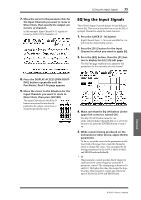
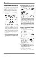
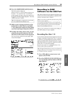
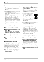
EQ'ing the Input Signals 35 7. Move the cursor to the parameter box for the Input Channels you want to route to Direct Outs, then specify the output connectors or channels. In this example, Input Channel 9-12 signals are routed to ADAT OUT channels 5-8. EQ'ing the Input Signals The 01V96i's Input Channels feature 4-band full parametric EQ. This section describes how to use the EQ of an Input Channel to adjust the tonal character. 1. Press the LAYER [1-16] button. Input Channel Layer 1-16 is now available for control from the channel strip section. 2. Press the [SEL] button for the Input Channel to which you want to apply EQ. 3. Press the [EQ] button, then the [F1] but- ton to display the EQ | EQ Edit page. The EQ Edit page enables you to adjust the EQ parameters for the currently-selected channel. 8. Press the DISPLAY ACCESS [PAN/ROUT- ING] button repeatedly until the Pan/Route | Rout1-16 page appears. 9. Move the cursor to the D button for the Input Channels you want to route to Direct Outs, then press [ENTER]. The Input Channels for which the D buttons are turned on are directly patched to the output connectors or channels specified in Step 7. 4. Make sure that the EQ ON button (in the upper-left corner) is turned ON. The EQ ON/OFF button turns the currently-selected Input Channel's EQ on or off. If the button is off, press the [ENTER] button to turn it on. 5. While sound is being produced on the instrument or other device, adjust the EQ parameters. To do so, move the cursor to the parameters in the lower half of the page, then rotate the Parameter wheel to change the values. You can adjust the following parameters for the LOW, L-MID, H-MID, and HIGH bands individually. •Q This parameter control specifies the Q (slope) for cut/boost of the center frequency set via the F parameter control. The setting range is between 10 and 0.10. The higher the value, the steeper the slope becomes. This parameter control also selects the type of EQ for the LOW and HIGH band. Tutorial 01V96i-Owner's Manual
-
 1
1 -
2
-
3
-
4
-
5
-
6
-
7
-
8
-
9
-
10
-
11
-
12
-
13
-
14
-
15
-
16
-
17
-
18
-
19
-
20
-
21
-
22
-
23
-
24
-
25
-
26
-
27
-
28
-
29
-
 30
30 -
 31
31 -
 32
32 -
 33
33 -
 34
34 -
 35
35 -
 36
36 -
 37
37 -
 38
38 -
 39
39 -
 40
40 -
41
-
42
-
43
-
44
-
45
-
46
-
47
-
48
-
49
-
50
-
51
-
52
-
53
-
54
-
55
-
56
-
57
-
58
-
59
-
60
-
61
-
62
-
63
-
64
-
65
-
66
-
67
-
68
-
69
-
70
-
71
 |
 |
