Yamaha 01V96i Owner's Manual - Page 25
Connections and Setup, Connections
 |
View all Yamaha 01V96i manuals
Add to My Manuals
Save this manual to your list of manuals |
Page 25 highlights
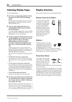
Connections and Setup This chapter explains how to connect and set up your 01V96i. Connections and Setup 25 Connections The following section explains two typical ways to connect the 01V96i to external equipment, although there are numerous others. ■ Configuring an analog 16-24-channel mixing system Synthesizer REC SONG SCENE MUSIC PRODUCTION SYNTHESIZER Integrated Sampling Sequencer Real-time External Control Sur face Modular Synthesis Plug-in System Synthesizer REC SONG SCENE MUSIC PRODUCTION SYNTHESIZER Integrated Sampling Sequencer Real-time External Control Sur face Modular Synthesis Plug-in System Optional AD card (adds 8 input channels) External recorder Effects processor Guitar SLOT INPUT connector OMNI OUT connector INPUT connector CH1-4 CH5-8 CH9-12 1 2 3 4 5 6 7 8 9 10 11 12 13 15 PHANTOM +48V A A A A A A A A A A A A 14 B B B B B B B B B B B B INPUT (BAL) INSERT OUT IN (UNBAL) INSERT I/O INSERT I/O INSERT I/O INSERT I/O INSERT I/O INSERT I/O INSERT I/O INSERT I/O INSERT I/O INSERT I/O INSERT I/O INSERT I/O L 16 R IN OUT 2TR -10dBV (UNBAL) PHONES CH15/16 2TR IN MONITOR 2TR IN PAD 20dB -16 -60 GAIN PEAK SIGNAL 20dB -16 -60 GAIN PEAK SIGNAL 20dB -16 -60 GAIN PEAK SIGNAL 20dB -16 -60 GAIN PEAK SIGNAL 20dB -16 -60 GAIN PEAK SIGNAL 20dB -16 -60 GAIN PEAK SIGNAL 20dB -16 -60 GAIN PEAK SIGNAL 20dB -16 -60 GAIN PEAK SIGNAL 20dB -16 -60 GAIN PEAK SIGNAL 20dB -16 -60 GAIN PEAK SIGNAL 20dB -16 -60 GAIN PEAK SIGNAL 20dB +4 GAIN -26 +4 GAIN -26 0 LEVEL10 -16 -60 GAIN +4 GAIN -26 +4 GAIN -26 MONITOR OUT PEAK SIGNAL 13 PEAK 14 15 PEAK 16 SIGNAL SIGNAL 0 LEVEL10 PHONES DISPLAY ACCESS SCENE MEMORY SCENE DIO/SETUP MIDI UTILITY / INSERT/ PAN/ PAIR/ DELAY ROUTING GROUP PATCH DYNAMICS EQ EFFECT FADER MODE VIEW AUX 1 AUX 2 AUX 3 AUX 4 AUX 5 AUX 6 AUX 7 AUX 8 HOME (METER) LAYER 1-16 17-32 MASTER REMOTE OVER 0 -3 -6 -9 -12 -15 -18 -24 -30 -36 -48 STEREO STORE DEC Q HIGH HIGH-MID FREQUENCY LOW-MID GAIN LOW ENTER RECALL SOLO CLEAR INC ST IN SEL SEL SEL SEL SEL SEL SEL SEL SEL SEL SEL SEL SEL SEL SEL SEL SEL SEL SEL 2TR IN connector 2TR OUT connector MONITOR OUT connectors SOLO SOLO SOLO SOLO SOLO SOLO SOLO SOLO SOLO SOLO SOLO SOLO SOLO SOLO SOLO SOLO SOLO SOLO ON ON ON ON ON ON ON ON ON ON ON ON ON ON ON ON 1 2 3 4 5 6 7 8 9 10 11 12 13 14 15 16 ON ON ON ST IN 1 ST IN 2 INPUT connector +10 0 +10 0 +10 0 +10 0 +10 0 +10 0 +10 0 +10 0 +10 0 +10 0 +10 0 +10 0 +10 0 +10 0 +10 0 +10 00 5 5 5 5 5 5 5 5 5 5 5 5 5 5 5 5 5 5 5 5 5 5 5 5 5 5 5 5 5 5 5 55 0 0 0 0 0 0 0 0 0 0 0 0 0 0 0 0 10 10 10 10 10 10 10 10 10 10 10 10 10 10 10 10 10 5 5 5 5 5 5 5 5 5 5 5 5 5 5 5 5 15 15 15 15 15 15 15 15 15 15 15 15 15 15 15 15 15 10 20 10 20 10 20 10 20 10 20 10 20 10 20 10 20 10 20 10 20 10 20 10 20 10 20 10 20 10 20 10 20 20 15 30 15 30 15 30 15 30 15 30 15 30 15 30 15 30 15 30 15 30 15 30 15 30 15 30 15 30 15 30 15 30 30 20 40 20 40 20 40 20 40 20 40 20 40 20 40 20 40 20 40 20 40 20 40 20 40 20 40 20 40 20 40 20 40 40 30 50 30 50 30 50 30 50 30 50 30 50 30 50 30 50 30 50 30 50 30 50 30 50 30 50 30 50 30 50 30 50 50 40 60 70 40 60 70 40 60 70 40 60 70 40 60 70 40 60 70 40 60 70 40 60 70 40 60 70 40 60 70 40 60 70 40 60 70 40 60 70 40 60 70 40 60 70 40 60 60 70 70 50 50 50 50 50 50 50 50 50 50 50 50 50 50 50 50 USER DEFINED KEYS 1 2 3 4 5 6 7 8 PHONES jack 1 17 AUX 1 2 18 AUX 2 3 19 AUX 3 4 20 AUX 4 5 21 AUX 5 6 22 AUX 6 7 23 AUX 7 8 24 AUX 8 9 25 BUS 1 10 26 BUS 2 11 27 BUS 3 12 28 BUS 4 13 29 BUS 5 14 30 BUS 6 15 31 BUS 7 16 32 BUS 8 STEREO VOL VOL Monitoring system This illustration shows a simple system with 16 analog channels using the 01V96i's INPUT connectors 1-16. If an optional AD card (such as the MY8-AD or MY8-AD96) is installed in the slot, up to 24 analog channels can be mixed. Tip: You can adjust the gain of the AD card channels by setting the DIP switches on the card. For more information, see your AD card documentation. Connections and Setup 01V96i-Owner's Manual
-
 1
1 -
2
-
3
-
4
-
5
-
6
-
7
-
8
-
9
-
10
-
11
-
12
-
13
-
14
-
15
-
16
-
17
-
18
-
19
-
 20
20 -
 21
21 -
 22
22 -
 23
23 -
 24
24 -
 25
25 -
 26
26 -
 27
27 -
 28
28 -
 29
29 -
 30
30 -
31
-
32
-
33
-
34
-
35
-
36
-
37
-
38
-
39
-
40
-
41
-
42
-
43
-
44
-
45
-
46
-
47
-
48
-
49
-
50
-
51
-
52
-
53
-
54
-
55
-
56
-
57
-
58
-
59
-
60
-
61
-
62
-
63
-
64
-
65
-
66
-
67
-
68
-
69
-
70
-
71
 |
 |
