Yamaha 01V96i Owner's Manual - Page 9
Control Surface & Rear Panel, Control Surface - master layer
 |
View all Yamaha 01V96i manuals
Add to My Manuals
Save this manual to your list of manuals |
Page 9 highlights
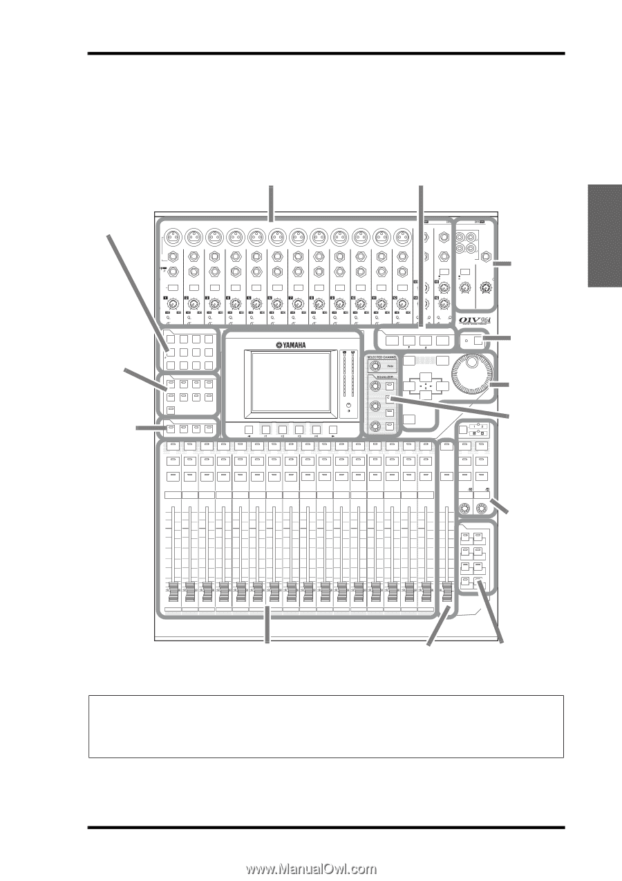
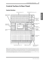
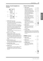
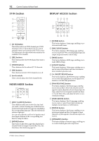
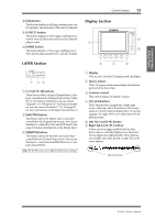
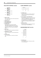
Control Surface & Rear Panel Control Surface & Rear Panel 9 Control Surface & Rear Panel Control Surface AD Input Section (p. 10) SCENE MEMORY Section (p. 14) DISPLAY ACCESS Section (p. 12) CH1-4 CH5-8 CH9-12 1 2 3 4 5 6 7 8 9 10 11 12 13 15 PHANTOM +48V A A A A A A A A A A A A 14 B B B B B B B B B B B B INPUT (BAL) INSERT OUT IN (UNBAL) INSERT I/O INSERT I/O INSERT I/O INSERT I/O INSERT I/O INSERT I/O INSERT I/O INSERT I/O INSERT I/O INSERT I/O INSERT I/O INSERT I/O L 16 R IN OUT 2TR -10dBV (UNBAL) PHONES CH15/16 2TR IN MONITOR 2TR IN PAD 20dB -16 -60 GAIN PEAK SIGNAL 20dB -16 -60 GAIN PEAK SIGNAL 20dB -16 -60 GAIN PEAK SIGNAL 20dB -16 -60 GAIN PEAK SIGNAL 20dB -16 -60 GAIN PEAK SIGNAL 20dB -16 -60 GAIN PEAK SIGNAL 20dB -16 -60 GAIN PEAK SIGNAL 20dB -16 -60 GAIN PEAK SIGNAL 20dB -16 -60 GAIN PEAK SIGNAL 20dB -16 -60 GAIN PEAK SIGNAL 20dB -16 -60 GAIN PEAK SIGNAL 20dB +4 GAIN -26 +4 GAIN -26 0 10 LEVEL -16 -60 GAIN +4 GAIN -26 +4 GAIN -26 MONITOR OUT PEAK SIGNAL 13 PEAK SIGNAL 14 15 PEAK SIGNAL 16 0 10 LEVEL PHONES DISPLAY ACCESS SCENE MEMORY FADER MODE Section (p. 12) LAYER Section (p. 13) SCENE DIO/SETUP MIDI UTILITY / INSERT/ PAN/ PAIR/ DELAY ROUTING GROUP PATCH DYNAMICS EQ EFFECT FADER MODE VIEW AUX 1 AUX 2 AUX 3 AUX 4 AUX 5 AUX 6 AUX 7 AUX 8 HOME (METER) LAYER 1-16 17-32 MASTER REMOTE Display Section (p. 13) OVER 0 -3 -6 -9 -12 -15 -18 -24 -30 -36 -48 STEREO STORE DEC Q HIGH HIGH-MID FREQUENCY LOW-MID GAIN LOW ENTER RECALL SOLO CLEAR INC ST IN SEL SEL SEL SEL SEL SEL SEL SEL SEL SEL SEL SEL SEL SEL SEL SEL SEL SEL SEL SOLO SOLO SOLO SOLO SOLO SOLO SOLO SOLO SOLO SOLO SOLO SOLO SOLO SOLO SOLO SOLO SOLO SOLO ON ON ON ON ON ON ON ON ON ON ON ON ON ON ON ON 1 2 3 4 5 6 7 8 9 10 11 12 13 14 15 16 ON ON ON ST IN 1 ST IN 2 +10 0 +10 0 +10 0 +10 0 +10 0 +10 0 +10 0 +10 0 +10 0 +10 0 +10 0 +10 0 +10 0 +10 0 +10 0 +10 00 5 5 5 5 5 5 5 5 5 5 5 5 5 5 5 5 5 5 5 5 5 5 5 5 5 5 5 5 5 5 5 55 0 0 0 0 0 0 0 0 0 0 0 0 0 0 0 0 10 10 10 10 10 10 10 10 10 10 10 10 10 10 10 10 10 5 5 5 5 5 5 5 5 5 5 5 5 5 5 5 5 15 15 15 15 15 15 15 15 15 15 15 15 15 15 15 15 15 10 20 10 20 10 20 10 20 10 20 10 20 10 20 10 20 10 20 10 20 10 20 10 20 10 20 10 20 10 20 10 20 20 15 30 15 30 15 30 15 30 15 30 15 30 15 30 15 30 15 30 15 30 15 30 15 30 15 30 15 30 15 30 15 30 30 20 40 20 40 20 40 20 40 20 40 20 40 20 40 20 40 20 40 20 40 20 40 20 40 20 40 20 40 20 40 20 40 40 30 50 30 50 30 50 30 50 30 50 30 50 30 50 30 50 30 50 30 50 30 50 30 50 30 50 30 50 30 50 30 50 50 40 60 70 40 60 70 40 60 70 40 60 70 40 60 70 40 60 70 40 60 70 40 60 70 40 60 70 40 60 70 40 60 70 40 60 70 40 60 70 40 60 70 40 60 70 40 60 60 70 70 50 50 50 50 50 50 50 50 50 50 50 50 50 50 50 50 USER DEFINED KEYS 1 2 3 4 5 6 7 8 1 17 AUX 1 2 18 AUX 2 3 19 AUX 3 4 20 AUX 4 5 21 AUX 5 6 22 AUX 6 7 23 AUX 7 8 24 AUX 8 9 25 BUS 1 10 26 BUS 2 11 27 BUS 3 12 28 BUS 4 13 29 BUS 5 14 30 BUS 6 15 31 BUS 7 16 32 BUS 8 STEREO Monitor Out & Headphones Section (p. 11) SOLO Section (p. 15) Data Entry Section (p. 15) SELECTED CHANNEL Section (p. 14) ST IN Section (p. 12) Channel Strip Section (p. 11) STEREO Section (p. 11) USER DEFINED KEYS Section (p. 14) Note: Screw holes for attaching a cover are located at both sides of the AD input section of the 01V96i. (Size M3, horizontal spacing 417 mm, vertical spacing 36 mm.) You may wish to fabricate your own cover and attach it to the front panel to prevent the controls from being operated inadvertently. Yamaha does not sell such a cover. If you fabricate and attach your own cover, make sure that the mounting screws do not extend more than 10 mm into the front panel. You will need to allow approximately 15-20 mm between the top panel and the cover in order to clear the control knobs and buttons. 01V96i-Owner's Manual
-
 1
1 -
2
-
3
-
 4
4 -
 5
5 -
 6
6 -
 7
7 -
 8
8 -
 9
9 -
 10
10 -
 11
11 -
 12
12 -
 13
13 -
 14
14 -
15
-
16
-
17
-
18
-
19
-
20
-
21
-
22
-
23
-
24
-
25
-
26
-
27
-
28
-
29
-
30
-
31
-
32
-
33
-
34
-
35
-
36
-
37
-
38
-
39
-
40
-
41
-
42
-
43
-
44
-
45
-
46
-
47
-
48
-
49
-
50
-
51
-
52
-
53
-
54
-
55
-
56
-
57
-
58
-
59
-
60
-
61
-
62
-
63
-
64
-
65
-
66
-
67
-
68
-
69
-
70
-
71
 |
 |