Yamaha 01V96i Owner's Manual - Page 17
Digital I/O MIDI/USB
 |
View all Yamaha 01V96i manuals
Add to My Manuals
Save this manual to your list of manuals |
Page 17 highlights
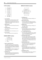
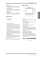
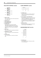
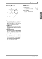
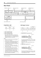
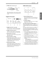
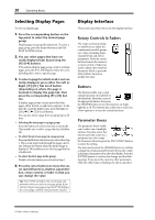
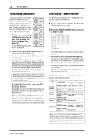
Control Surface & Rear Panel Rear Panel 17 3 STEREO OUT connectors L/R Female XLR plug 2 (hot) 3 (cold) MIDI/USB Section 1 (ground) These balanced XLR-3-32-type connectors output the Stereo Out signals. The nominal signal level is +4 dB. Digital I/O Section 12 3 45 1 WORD CLOCK OUT connector This BNC connector outputs a wordclock signal from the 01V96i to a connected external device. 2 WORD CLOCK IN connector This BNC connector inputs a wordclock signal from a connected external device to the 01V96i. 3 ADAT IN/OUT connectors These optical connectors input and output ADAT digital audio signals. 4 2TR OUT DIGITAL COAXIAL This RCA phono connector outputs consumer format (IEC 60958) digital audio. The connector is typically used to connect the digital stereo input (consumer format) of a DAT recorder, MD recorder, or CD recorder. 5 2TR IN DIGITAL COAXIAL This RCA phono connector accepts consumer format (IEC 60958) digital audio. The connector is typically used to connect the digital stereo output (consumer format) of a DAT recorder, MD recorder, or CD recorder. 1 2 1 MIDI IN/THRU/OUT ports These standard MIDI IN, OUT and THRU ports enable you to connect the 01V96i to other MIDI equipment. 2 TO HOST USB port This USB port enables you to connect a computer equipped with a USB 2.0 port. Note when using the TO HOST USB port When connecting the 01V96i to a computer via the TO HOST USB port, please take the following measures. If you fail to take these measures, your computer or the 01V96i may stop operating (hang up), or data may be lost or damaged. If the computer or console stops operating, turn the power off and on again, and reboot the computer. • Before connecting the TO HOST USB port to your computer, disable the power conservation (suspend/sleep/standby/hibernate) settings of your computer. • Connect the TO HOST USB port to the computer before you power-on the console. • Before powering the console on/off or connecting/disconnecting the USB cable, you must do the following. - Close all applications. - Make sure that the console is not transmitting data. (The console also transmits data when you operate its buttons or move its faders.) • Leave an interval of at least six seconds between powering the console off and on, or between disconnecting and reconnecting the USB cable. 01V96i-Owner's Manual
-
 1
1 -
2
-
3
-
4
-
5
-
6
-
7
-
8
-
9
-
10
-
11
-
 12
12 -
 13
13 -
 14
14 -
 15
15 -
 16
16 -
 17
17 -
 18
18 -
 19
19 -
 20
20 -
 21
21 -
 22
22 -
23
-
24
-
25
-
26
-
27
-
28
-
29
-
30
-
31
-
32
-
33
-
34
-
35
-
36
-
37
-
38
-
39
-
40
-
41
-
42
-
43
-
44
-
45
-
46
-
47
-
48
-
49
-
50
-
51
-
52
-
53
-
54
-
55
-
56
-
57
-
58
-
59
-
60
-
61
-
62
-
63
-
64
-
65
-
66
-
67
-
68
-
69
-
70
-
71
 |
 |
