Yamaha PM5000 Owner's Manual - Page 13
G/A Group/Aux Master Out, Stereo Output and Mono Output - midi
 |
View all Yamaha PM5000 manuals
Add to My Manuals
Save this manual to your list of manuals |
Page 13 highlights
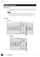
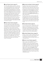
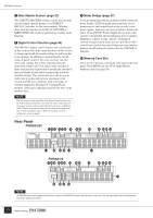
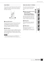
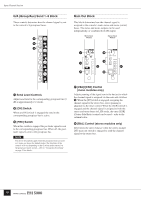
PM5000 Overview ! Mono (Stereo) Inputs XLR-type input connectors, DIRECT OUT connectors, and INSERT IN and OUT connectors are provided on each input channel. Stereo modules feature separate connectors for the L and R channels, but do not have DIRECT OUT connectors. @ Sub Inputs Each stereo aux master has L and R stereo aux SUB IN connectors, each group/aux master has G/A SUB IN connectors, both monitor outputs feature stereo 2TR IN (1 & 2) and L/C/R CUE SUB IN connectors, and the stereo and mono master outputs have L and R ST SUB IN and MONO(C) SUB IN connectors. L and R MATRIX SUB IN connectors are also provided for all matrix outputs. Please check the supplied block diagram for details. NOTE Stereo aux SUB IN and G/A SUB IN connectors are not provided on the PM5000-28. # Insert Inputs and Outputs Insert input and output connectors are provided on all 12 stereo aux masters, 8 group/aux masters, the stereo and mono masters, and the 4 stereo matrix and 8 mono matrix outputs. $ Stereo Aux Master Out % G/A (Group/Aux) Master Out ^ Matrix Out The stereo aux master, G/A (group/aux) master, and matrix output connectors are grouped together here. & Monitor Out These are the console's two stereo monitor outputs (A & B). You can use outputs A and B as separate stereo monitor outputs, or use A and B simultaneously for LCR monitoring (MONITOR B = Center). * Talkback/Oscillator Out The talkback or oscillator signal appears at this output. ( Stereo Output and Mono Output These are the stereo and mono master outputs (ST OUT, MONO (C)). º Lamp Connectors The supplied gooseneck lamps can be connected here (4 connectors on the PM5000-52C, 3 on the PM5000-36 and PM5000-28). Lamp brightness can be adjusted via the [LAMP DIMMER] control on the meter bridge. Engage the [LAMP OFF] switch to turn the lamps off. ¡ Fan Vents These are the air vents for the console's internal cooling fans (4 locations on the PM5000-52C, 3 on the PM500036 and PM5000-28). Be sure that the vents aren't blocked when installing the console. ™ Fan Switch Sets the speed of the console's internal cooling fans to match prevailing operating conditions. Normally the [LOW] setting can be used. When the ambient temperature is high, however, such as in some outdoor applications when the console is exposed to direct sunlight, the [HIGH] setting should be used. Also switch to the [HIGH] setting if the top-panel temperature feels higher than normal. £ +48V Master Switch This is the master switch for the 48-volt phantom power supply to all input channels. When using phantom power use the individual input channel [+48V] switches to turn phantom power on or off as required. ¢ External Expansion Connectors Type A and B CASCADE connectors, a D-sub 25-pin GPI connector, and MIDI IN/OUT/THRU connectors for connection to compatible external equipment. ∞ Power Supply Connector The dedicated external PW5000 power supply unit must be connected to this connector using the power supply cable supplied with the PM5000 console. 13
-
 1
1 -
2
-
3
-
4
-
5
-
6
-
7
-
 8
8 -
 9
9 -
 10
10 -
 11
11 -
 12
12 -
 13
13 -
 14
14 -
 15
15 -
 16
16 -
 17
17 -
 18
18 -
19
-
20
-
21
-
22
-
23
-
24
-
25
-
26
-
27
-
28
-
29
-
30
-
31
-
32
-
33
-
34
-
35
-
36
-
37
-
38
-
39
-
40
-
41
-
42
-
43
-
44
-
45
-
46
-
47
-
48
-
49
-
50
-
51
-
52
-
53
-
54
-
55
-
56
-
57
-
58
-
59
-
60
-
61
-
62
-
63
-
64
-
65
-
66
-
67
-
68
-
69
-
70
-
71
-
72
-
73
-
74
-
75
-
76
-
77
-
78
-
79
-
80
-
81
-
82
-
83
-
84
-
85
-
86
-
87
-
88
-
89
-
90
-
91
-
92
-
93
-
94
-
95
-
96
-
97
-
98
-
99
-
100
-
101
-
102
-
103
-
104
-
105
-
106
 |
 |
