Yamaha PM5000 Owner's Manual - Page 18
G/A (Group/Aux) Send 1~8 Block, Main Out Block, Send Level Controls, ON] Switch, mono modules only
 |
View all Yamaha PM5000 manuals
Add to My Manuals
Save this manual to your list of manuals |
Page 18 highlights
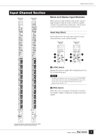
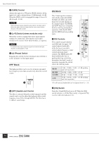
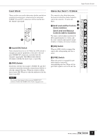
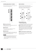
Input Channel Section G/A (Group/Aux) Send 1~8 Block These controls determine how the channel signal is sent to the console's 8 group/aux buses. $ % ^ Main Out Block This block determines how the channel signal is assigned to the console's main stereo and mono (center) buses. The stereo and mono outputs can be used independently, or combined for LCR output. Mono Input Module Stereo Input Module & * ( ( ¡ ¡ º º $ Send Level Controls Adjust send level to the corresponding group/aux bus (0 dB at approximately 2 o'clock). % [ON] Switch When an [ON] switch is engaged the send to the corresponding group/aux bus is active. ^ [PRE] Switch When this switch is engaged the pre-fader signal is sent to the corresponding group/aux bus. When off, the postfader signal is sent to the group/aux bus. NOTE The above descriptions apply when the group/aux buses are used as 8 mono aux buses (the default mode). The functions of the controls will vary depending on the G/A bus mode selected via the group/aux master section - refer to "Group/Aux Switching" on page 32 for details. & [PAN]/[CSR] Control (mono modules only) Adjusts panning of the signal sent to the bus(es) to which the channel signal is assigned via the main out switches (. When the [ST] switch is engaged, assigning the channel signal to the stereo bus, stereo panning is adjusted via the inner control. When the [LCR] switch is engaged and the channel signal is assigned to both the stereo and mono buses in LCR mode, the outer [CSR] (Center-Side Ratio) control can be used - refer to the column below. * [BAL] Control (stereo modules only) Determines the stereo balance when the stereo-module [ST] main out switch is engaged to send the channel signal to the stereo bus. 18
-
 1
1 -
2
-
3
-
4
-
5
-
6
-
7
-
8
-
9
-
10
-
11
-
12
-
 13
13 -
 14
14 -
 15
15 -
 16
16 -
 17
17 -
 18
18 -
 19
19 -
 20
20 -
 21
21 -
 22
22 -
 23
23 -
24
-
25
-
26
-
27
-
28
-
29
-
30
-
31
-
32
-
33
-
34
-
35
-
36
-
37
-
38
-
39
-
40
-
41
-
42
-
43
-
44
-
45
-
46
-
47
-
48
-
49
-
50
-
51
-
52
-
53
-
54
-
55
-
56
-
57
-
58
-
59
-
60
-
61
-
62
-
63
-
64
-
65
-
66
-
67
-
68
-
69
-
70
-
71
-
72
-
73
-
74
-
75
-
76
-
77
-
78
-
79
-
80
-
81
-
82
-
83
-
84
-
85
-
86
-
87
-
88
-
89
-
90
-
91
-
92
-
93
-
94
-
95
-
96
-
97
-
98
-
99
-
100
-
101
-
102
-
103
-
104
-
105
-
106
 |
 |
