Yamaha PM5000 Owner's Manual - Page 24
VCA Master and Master Mute Switch Group Control, VCA
 |
View all Yamaha PM5000 manuals
Add to My Manuals
Save this manual to your list of manuals |
Page 24 highlights
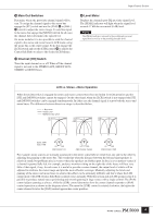
Input Channel Section VCA Master and Master Mute Switch Group Control If a number of input channels are assigned to VCA masters or mute master switches as described in the preceding section, those channels can be controlled as a group from a single fader or mute switch. VCA Section VCA master faders 1 ~ 12 function as group faders for the assigned input channels, adjusting the output level of all assigned channels while maintaining the level relationships between them. The final fader level of each channel will be the sum of the channel fader and VCA fader settings. In the example below input channels 1, 3, 5, and 7 are assigned to VCA group 1 while input channels 1 through 4 are assigned to the VCA 2 group. VCA Faders Channel Faders VCA 1 VCA 2 1 2 3 4 5 6 7 Since the VCA 1 fader is set to -20 dB and the VCA 2 fader is set to 0 dB, the final fader levels of channels 1 and 3, which are assigned to both VCA 1 and VCA 2, will 20-dB lower than the input channel fader settings. Since the VCA 2 fader is set to 0 dB (nominal), the final fader levels of input channels 2 and 4 will correspond exactly to their respective channel fader settings. In the same way, the [VCA MUTE] switches on the VCA master modules function as group mute switches for the assigned input channels. VCA Faders Channel Faders [VCA MUTE] Switch VCA 1 VCA 2 1 2 3 4 5 6 7 Since the VCA 2 [VCA MUTE] switch is engaged the final fader level of input channels 1 ~ 4 will be -∞. NOTE The [VCA MUTE] switches function in a slightly different way than the mute master switches. When a [VCA MUTE] switch is engaged the effect is the same as turning that VCA fader all the way down to -∞. The mute master switches, on the other hand, disengage the channel [ON] switches of the assigned channels. 24
-
 1
1 -
2
-
3
-
4
-
5
-
6
-
7
-
8
-
9
-
10
-
11
-
12
-
13
-
14
-
15
-
16
-
17
-
18
-
 19
19 -
 20
20 -
 21
21 -
 22
22 -
 23
23 -
 24
24 -
 25
25 -
 26
26 -
 27
27 -
 28
28 -
 29
29 -
30
-
31
-
32
-
33
-
34
-
35
-
36
-
37
-
38
-
39
-
40
-
41
-
42
-
43
-
44
-
45
-
46
-
47
-
48
-
49
-
50
-
51
-
52
-
53
-
54
-
55
-
56
-
57
-
58
-
59
-
60
-
61
-
62
-
63
-
64
-
65
-
66
-
67
-
68
-
69
-
70
-
71
-
72
-
73
-
74
-
75
-
76
-
77
-
78
-
79
-
80
-
81
-
82
-
83
-
84
-
85
-
86
-
87
-
88
-
89
-
90
-
91
-
92
-
93
-
94
-
95
-
96
-
97
-
98
-
99
-
100
-
101
-
102
-
103
-
104
-
105
-
106
 |
 |
