Yamaha PM5000 Owner's Manual - Page 20
Channel Fader Block, Channel Fader, RECALL SAFE] Switch, FADER SAFE] Switch, VCA Indicators 1~12 - 52
 |
View all Yamaha PM5000 manuals
Add to My Manuals
Save this manual to your list of manuals |
Page 20 highlights
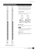
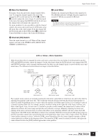
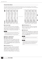
Input Channel Section Channel Fader Block The channel faders determine the level of the channel signal sent to the console's master buses, and are of primary importance in setting up the balance between the various channels in the mix. The channel faders can also be assigned to specific VCA and mute groups for group level and mute control. £ ¢ ∞ ™ ¶ ™ Channel Fader Adjusts the out signal level from the corresponding channel. The channel faders also affect the signal level sent to the stereo aux and group/aux buses when the [PRE] switches associated with the corresponding sends are off (i.e. they are sending the post-fader signal). NOTE The channel faders are motor-drive types that will physically move to the memorized settings when a scene memory is recalled - after the specified "fade time," if one has been programmed. Refer to "Scene Memory Functions" on page 51 for details. £ [RECALL SAFE] Switch ¢ [FADER SAFE] Switch Either of these switches can be engaged to prevent the corresponding data from changing the channel settings when a scene memory is recalled. Use the [RECALL SAFE] switch to maintain the master bus assign switch settings, or [FADER SAFE] switch to maintain the level of the channel fader. ∞ VCA Indicators 1~12 Indicate the VCA groups to which the corresponding channel fader is assigned. If a VCA group master to which the channel is assigned is muted via its [VCA MUTE] switch, the corresponding VCA indicator will flash rather than light continuously. More details are provided in the "Channel Grouping" section on page 21. § § MUTE Indicators 1~8 Indicate the mute groups to which the corresponding channel is assigned. More details are provided in the "Channel Grouping" section. ¶ [CUE] Switch When this switch is engaged the pre-fader channel signal is sent to the console's CUE L&R buses regardless of the channel's on/off status. The cue signal can be monitored via the rear-panel MONITOR OUT connectors or any of the console's PHONES jacks. NOTE Using the VCA CUE function, the post-fader channel signal can be monitored. NOTE The [CUE] switches are also used to assign channels to VCA and mute groups (page 21), as well as to specify target channels when setting fade time parameters (page 52). Normal [CUE] switch function is suspended while any of these operations are in progress. 20
-
 1
1 -
2
-
3
-
4
-
5
-
6
-
7
-
8
-
9
-
10
-
11
-
12
-
13
-
14
-
 15
15 -
 16
16 -
 17
17 -
 18
18 -
 19
19 -
 20
20 -
 21
21 -
 22
22 -
 23
23 -
 24
24 -
 25
25 -
26
-
27
-
28
-
29
-
30
-
31
-
32
-
33
-
34
-
35
-
36
-
37
-
38
-
39
-
40
-
41
-
42
-
43
-
44
-
45
-
46
-
47
-
48
-
49
-
50
-
51
-
52
-
53
-
54
-
55
-
56
-
57
-
58
-
59
-
60
-
61
-
62
-
63
-
64
-
65
-
66
-
67
-
68
-
69
-
70
-
71
-
72
-
73
-
74
-
75
-
76
-
77
-
78
-
79
-
80
-
81
-
82
-
83
-
84
-
85
-
86
-
87
-
88
-
89
-
90
-
91
-
92
-
93
-
94
-
95
-
96
-
97
-
98
-
99
-
100
-
101
-
102
-
103
-
104
-
105
-
106
 |
 |
