Yamaha PM5000 Owner's Manual - Page 16
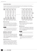
HPF Block, EQ Block, GAIN] Control, L+R] Switch stereo modules only, ø] Phase Switch - hi level
 |
View all Yamaha PM5000 manuals
Add to My Manuals
Save this manual to your list of manuals |
Page 16 highlights
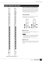
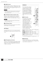
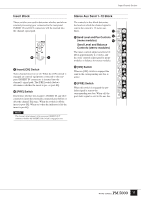
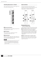
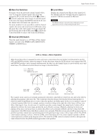
Input Channel Section 3 [GAIN] Control Adjusts the input level. When the [PAD] switch is off the input level can be adjusted from -10 dB through -60 dB. When the [PAD] switch is engaged the range is from +16 dB through -34 dB. NOTE Stereo modules feature concentric gain controls: the inner control adjusts the gain of the left channel and the outer control adjusts the gain of the right channel. 4 [L+R] Switch (stereo modules only) When this switch is engaged the stereo input signal is summed to a mono mix, allowing the stereo input modules to be used as mono input modules, as required. NOTE To maintain the proper subjective signal level the left and right channels are attenuated by 3 dB. 5 [ø] (Phase) Switch Engaging this switch reverses the phase (also referred to as the "polarity") of the input signal. HPF Block The high-pass filter can be used to attenuate unwanted low-frequency noise that can adversely affect the overall sound. 6 6 [HPF] Switch and Control The filter is activated when the switch engaged, and the control can be used to adjust the high-pass filter cutoff frequency from 20 Hz through 400 Hz. The filter has a 12-dB/oct. cutoff slope. EQ Block This 4-band equalizer features individually-adjustable HIGH, HI-MID, LO-MID, and LOW bands for versatile shaping of the channel signal. The HIGH and LOW bands are switchable between shelving and peaking operation, while the HI-MID and LO-MID bands are peaking types. 7 7 EQ Controls Two controls are provided for each EQ band: the upper "Q" control adjusts bandwidth, while the lower concentric control adjusts frequency (outer control) and gain (inner control). The HIGH and LOW 8 bands additionally have a peaking/shelving switch that determines the band's mode of operation: engaging the switch selects the shelving mode. HIGH HI-MID LO-MID LOW 1 kHz ~ 20 kHz, -15 dB ~ +15 dB (peaking and shelving modes) 400 Hz ~ 8 kHz, -15 dB ~ +15 dB 80 Hz ~ 1.6 kHz, -15 dB ~ +15 dB 30 Hz ~ 600 Hz, -15 dB ~ +15 dB (peaking and shelving modes) * For all bands Q (bandwidth) can be adjusted from 0.5 ~ 3.0. 8 [EQ] Switch Turns the 4-band EQ block on or off. When the [EQ] switch indicator is off the EQ circuitry is bypassed. EQ is active when the indicator is lit. 16
-
 1
1 -
2
-
3
-
4
-
5
-
6
-
7
-
8
-
9
-
10
-
 11
11 -
 12
12 -
 13
13 -
 14
14 -
 15
15 -
 16
16 -
 17
17 -
 18
18 -
 19
19 -
 20
20 -
 21
21 -
22
-
23
-
24
-
25
-
26
-
27
-
28
-
29
-
30
-
31
-
32
-
33
-
34
-
35
-
36
-
37
-
38
-
39
-
40
-
41
-
42
-
43
-
44
-
45
-
46
-
47
-
48
-
49
-
50
-
51
-
52
-
53
-
54
-
55
-
56
-
57
-
58
-
59
-
60
-
61
-
62
-
63
-
64
-
65
-
66
-
67
-
68
-
69
-
70
-
71
-
72
-
73
-
74
-
75
-
76
-
77
-
78
-
79
-
80
-
81
-
82
-
83
-
84
-
85
-
86
-
87
-
88
-
89
-
90
-
91
-
92
-
93
-
94
-
95
-
96
-
97
-
98
-
99
-
100
-
101
-
102
-
103
-
104
-
105
-
106
 |
 |
