Yamaha PM5000 Owner's Manual - Page 17
Insert Block, Stereo Aux Send 1~12 Block, Insert [ON] Switch, PRE] Switch, Send Level and Pan Controls
 |
View all Yamaha PM5000 manuals
Add to My Manuals
Save this manual to your list of manuals |
Page 17 highlights
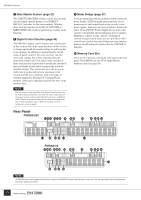
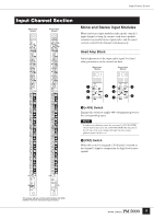
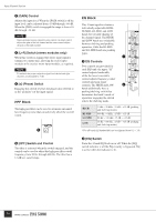
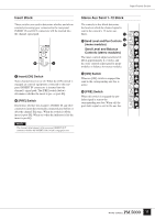
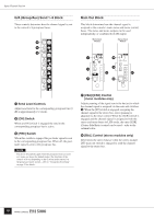
Input Channel Section Insert Block These switches are used to determine whether and where external processing gear connected to the rear-panel INSERT IN and OUT connectors will be inserted into the channel signal path. ) 9 9 Insert [ON] Switch Turns channel insert on or off. When the [ON] switch is engaged an external equipment connected to the rearpanel INSERT IN connectors is inserted into the channel's signal path. The [PRE] switch (below) determines whether the insert is pre- or post-EQ. ) [PRE] Switch Determines whether the channel's INSERT IN and OUT connectors insert the externally connected gear before or after the channel EQ stage. When the switch is off the insert is post-EQ. When on (when the indicator is lit) the insert is pre-EQ. NOTE The channel signal appears at the rear-panel INSERT OUT connector whether the INSERT [ON] switch is engaged or not. Stereo Aux Send 1~12 Block The controls in this block determine the levels at which the channel signal is sent to the console's 12 stereo aux buses. ! ! Send Level and Pan Controls @ (mono modules) # Send Level and Balance Controls (stereo modules) The inner controls adjust send level (0 dB at approximately 2 o'clock), and the outer controls adjust pan for mono modules or balance for stereo modules. @ [ON] Switch When an [ON] switch is engaged the send to the corresponding aux bus is active. # [PRE] Switch When this switch is engaged the prefader signal is sent to the corresponding aux bus. When off, the post-fader signal is sent to the aux bus. 17
-
 1
1 -
2
-
3
-
4
-
5
-
6
-
7
-
8
-
9
-
10
-
11
-
 12
12 -
 13
13 -
 14
14 -
 15
15 -
 16
16 -
 17
17 -
 18
18 -
 19
19 -
 20
20 -
 21
21 -
 22
22 -
23
-
24
-
25
-
26
-
27
-
28
-
29
-
30
-
31
-
32
-
33
-
34
-
35
-
36
-
37
-
38
-
39
-
40
-
41
-
42
-
43
-
44
-
45
-
46
-
47
-
48
-
49
-
50
-
51
-
52
-
53
-
54
-
55
-
56
-
57
-
58
-
59
-
60
-
61
-
62
-
63
-
64
-
65
-
66
-
67
-
68
-
69
-
70
-
71
-
72
-
73
-
74
-
75
-
76
-
77
-
78
-
79
-
80
-
81
-
82
-
83
-
84
-
85
-
86
-
87
-
88
-
89
-
90
-
91
-
92
-
93
-
94
-
95
-
96
-
97
-
98
-
99
-
100
-
101
-
102
-
103
-
104
-
105
-
106
 |
 |
