ZyXEL Omni TA 128 User Guide - Page 17
Installing your TA128
 |
View all ZyXEL Omni TA 128 manuals
Add to My Manuals
Save this manual to your list of manuals |
Page 17 highlights
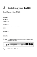
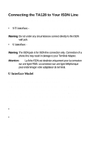
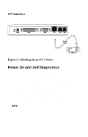
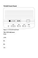
2 Installing your TA128 Back Panel of the TA128 You will find the following switch and connectors on the back panel of the TA128: See the figure below: ON/OFF - Power switch; turns the TA128 ON or OFF. POWER - Input terminal for power adapter. To DTE 1 - Serial port DB25 female connector for connection to the serial port of a DTE (computer/terminal). To DTE 2 - Serial port DB9 female connector for connection to the serial port of a DTE (computer/terminal). ISDN - ISDN RJ-45 terminal jack; connects to a S/T interface or a U interface (depending on the TA128 model purchased). PHONE 1 - RJ-11 terminal jack for analog adapter 1; for connecting to analog equipment. (phone, fax, answering machine, etc.) PHONE 2 - RJ-11 terminal jack for analog adapter 2; for connecting to analog equipment. O NOTE: The signal-pin assignment of the RJ-45 and RJ-11 phone jacks are listed in Chapter 18 . Figure 2 -1 TA128 Back Panel 5
-
 1
1 -
2
-
3
-
4
-
5
-
6
-
7
-
8
-
9
-
10
-
11
-
 12
12 -
 13
13 -
 14
14 -
 15
15 -
 16
16 -
 17
17 -
 18
18 -
 19
19 -
 20
20 -
 21
21 -
 22
22 -
23
-
24
-
25
-
26
-
27
-
28
-
29
-
30
-
31
-
32
-
33
-
34
-
35
-
36
-
37
-
38
-
39
-
40
-
41
-
42
-
43
-
44
-
45
-
46
-
47
-
48
-
49
-
50
-
51
-
52
-
53
-
54
-
55
-
56
-
57
-
58
-
59
-
60
-
61
-
62
-
63
-
64
-
65
-
66
-
67
-
68
-
69
-
70
-
71
-
72
-
73
-
74
-
75
-
76
-
77
-
78
-
79
-
80
-
81
-
82
-
83
-
84
-
85
-
86
-
87
-
88
-
89
-
90
-
91
-
92
-
93
-
94
-
95
-
96
-
97
-
98
-
99
-
100
-
101
-
102
-
103
-
104
-
105
-
106
-
107
-
108
-
109
-
110
-
111
-
112
-
113
-
114
-
115
-
116
-
117
-
118
-
119
-
120
-
121
-
122
-
123
-
124
-
125
-
126
-
127
-
128
-
129
-
130
-
131
-
132
-
133
-
134
-
135
-
136
-
137
-
138
-
139
-
140
-
141
-
142
-
143
-
144
-
145
-
146
-
147
-
148
-
149
-
150
-
151
-
152
-
153
-
154
-
155
-
156
-
157
-
158
-
159
-
160
-
161
-
162
-
163
-
164
-
165
-
166
-
167
-
168
-
169
-
170
-
171
-
172
-
173
 |
 |